140
Proprietary Information: Not for use or disclosure except by written agreement with Calix.
© Calix. All Rights Reserved.
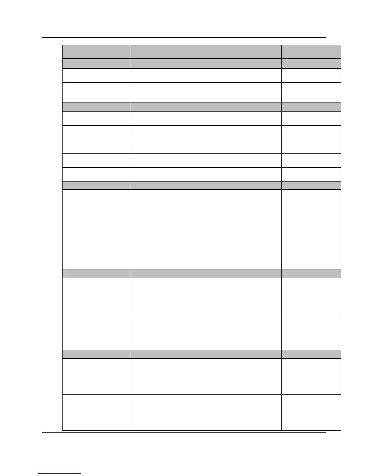
Parameter Description Valid Options
Upstream Power Back-off (UPBO)**
Band 1-4 parameter A-B Downstream or upstream rate adaptation mode for DSL port. 40.00-80.95
Kl
0
Upstream PBO electrical length, in dB. 0.0-128.0
no-force ‡
Downstream Power Back-off (DPBO)***
ESEL Exchange-to cabinet electrical length, in dB. 0.0-255.5
Exchange-side cable model parameter A-C, in dB.
MUS Minimum usable receive PSD mask, in dBm/Hz. -127.5 to 0.0
0 ‡
FMIN Downstream Power Back Off (PBO) minimum subcarrier base
FMAX Downstream PBO maximum subcarrier base frequency in kHz. 138-29997.75
Downstream PBO Breakpoints (DPBOEPSD)
Frequency 1-16 Specifies a list of up to 16 breakpoints that define the Power
Spectral Density Limit Mask being used at the exchange site
(reference G.997.1, section 7.3.1.2.13, DPBOEPSD). For example,
if the exchange site is using ADSL2+, Annex-A, non-overlapped,
these breakpoints should be set to match the diagram in G.992.5,
section A.1.3, figure A.2/G.992.5.
Each breakpoint is defined by a frequency:psd pair, where
frequency is in kHz and psd is in dBm/Hz. The system rounds the
input values to the nearest subcarrier (spaced at 4.3125 kHz). The
power will be rounded to the nearest 0.5 dBm/Hz.
4.3125 – 29997.75
PSD mask level 1-16 PSD mask level, in dBm/Hz. -127.5 to 0.0
0 ‡
Band 1-16 Start Specifies the start frequency (in KHz) for RFI bands 1 to 16 where
each frequency is an integer and has a resolution of 1 kHz. The
start and stop frequencies define the limits of a low-power band.
The system converts the input values to the closest encompassing
DMT subcarrier pair (i.e. multiples of 4.3125 kHz). The default value
0 ‡ - 1000000
Band 1-16 End Specifies the stop frequency (in KHz) for RFI bands 1 to 16. An RFI
band is entered as a start-
stop frequency pair where each frequency
is an integer and has a resolution of 1 kHz. These frequencies
define the limits of a low-power band. The system converts the input
values to the closest encompassing DMT subcarrier pair (i.e.
multiples of 4.3125 kHz). The default value is 0 (unused).
Band 1-4 Start Specifies the start frequencies (in kHz) for gap bands 1 to 4. A GAP
band is entered as a start-stop frequency pair where each frequency
is an integer and has a resolution of 1 kHz. These frequencies
define the limits of a no-power band. The system converts the input
values to the closest encompassing DMT subcarrier pair (i.e.
multiples of 4.3125 kHz). The default value is 0 (unused).
0 ‡ - 1000000
Band 1-4 End Specifies the stop frequencies (in kHz) for gap bands 1 to 4. A GAP
band is entered as a start-
stop frequency pair where each frequency
is an integer and has a resolution of 1 kHz. These frequencies
define the limits of a no-power band. The system converts the input
values to the closest encompassing DMT subcarrier pair (i.e.
multiples of 4.3125 kHz). The default value is 0 (unused).