33
Proprietary Information: Not for use or disclosure except by written agreement with Calix.
© Calix. All Rights Reserved.
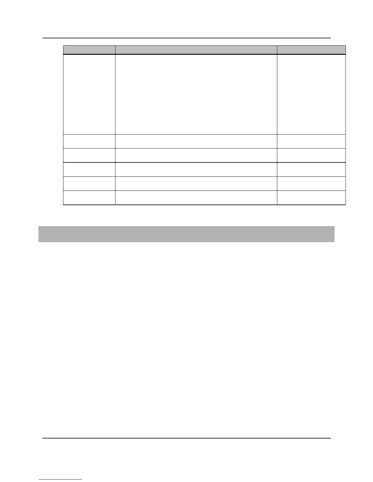
Interface Quality
Audit Mode
Mode to periodically check the number of File Check Sequence (FCS)
errors received as a percentage of total frames received on an interface.
An interface that exceeds the provisioned thresholds can be set to one
of the following modes:
no-audit - disables the Interface Quality Audit (IQA) mode
alarm-only - generates an alarm, but, does not take any action on
the interface
disable-interface – Disable the interface when the threshold is
exceeded
protocol-action – For ERPS and LAG, only disable the interface if
there is an alternate path that is up and available. For non-ERPS
and non-LAG interfaces, this is interpreted as “alarm only.”
no-audit, alarm-only ‡,
protocol-action, disable-
interface
Polling Interval Number of seconds between interface quality audits that compare
errored frames to total received frames.
Error Threshold Number of errored frames per million total frames to consider a specific
Polling Window Number of interface quality audit intervals to consider for failure
Number of failed audit quality intervals within the polling window that will
indicate an interface failure for IQA to take an alarm or OOS action.
Interval Min Frames Minimum number of frames that must be received per interval for a
specific interval to be considered valid.
* Required field
‡ Default
To configure an Ethernet port associated interface for service
1. On the Navigation Tree, click a GE or 10GE port where you want to configure an
associated interface.
2. In the Work Area, click Associated Interface > Provisioning.
3. Reference the table above to configure the parameters.
4. Click Apply.
For CLI:
set interface <interface name> [eth-svc|role|description|subscriber-
id|native-vlan|mtu|rstp-active|rstp-prio|rstp-path-cost|rstp-bpdu-mac|rstp-
edge|bpdu-guard|immediate-leave|ingress-policy-map|split-horizon-fwd|lag-
mode|lacp-role|lacp-hash-method|lacp-min-ports|lacp-max-ports|lacp-system-
priority|lag-cross-card|lag-cross-card-revert|trusted|ethertype|admin-state]
Configuring a Link Aggregation Interface
This topic describes how to configure an Ethernet interface and a Link Aggregation Group
(LAG) interface. E7 Ethernet interfaces are logical objects that represent the service-related
attributes of an Ethernet port.
E7 Ethernet ports and the associated Ethernet interfaces always exist and can only be
modified. LAG interfaces and their association with E7 Ethernet ports can be created,
deleted, and modified.