Proprietary*Information:*Not*for*use*or*disclosure*except*by*written*agreement*with*Calix.*
"!#$%&'(!)%%!*&+,-.!*/./01/2(!
Verify that the following items are on hand before you begin the installation.
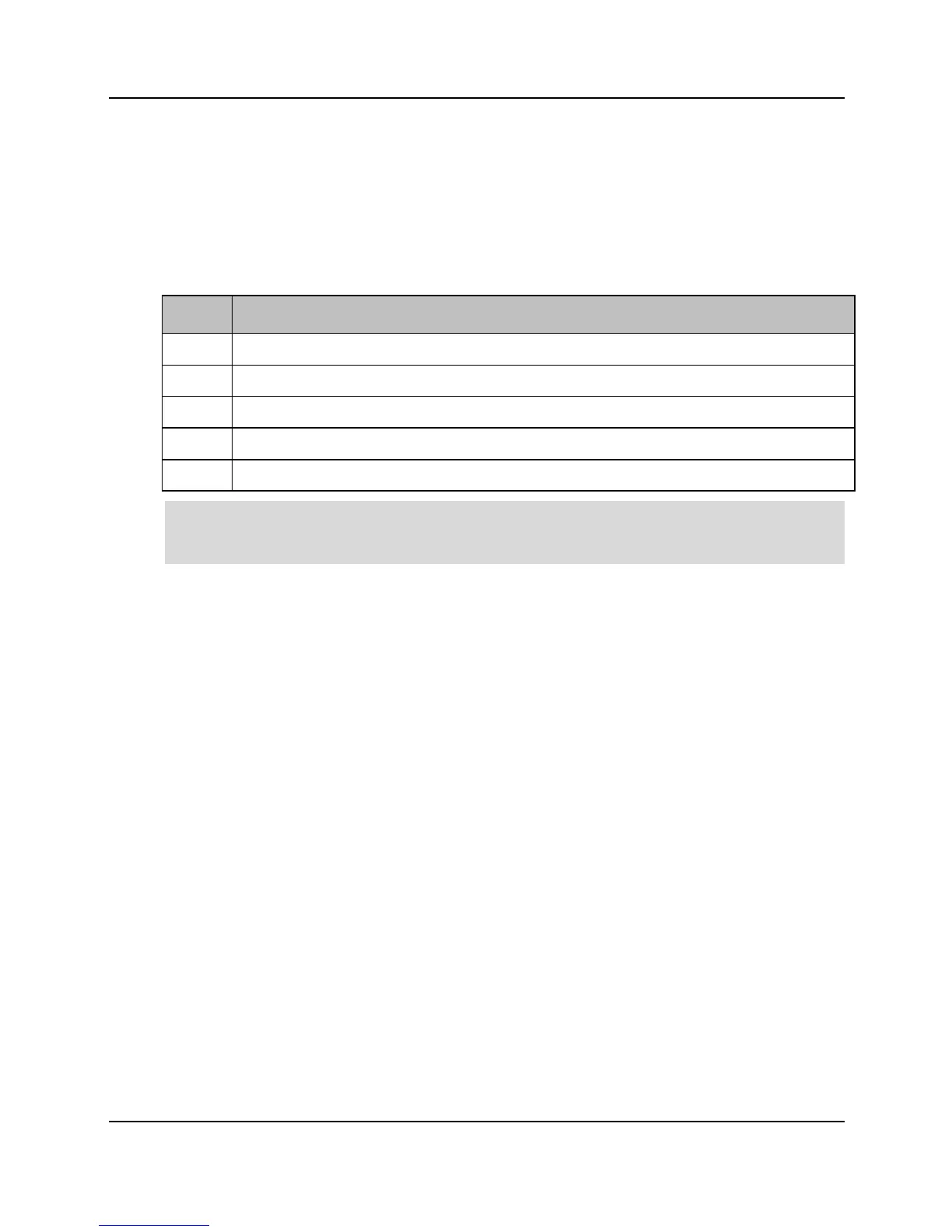
The Calix E7-20 installation package includes the following items:
Calix E7-20 twenty-slot chassis (13 RU)
Calix E7-20 fan tray assembly
Calix E7-20 fan tray assembly air filter
Calix E7-20 fiber management system
Rack mounting installation kit
Note: Pluggable transceiver modules (required for line termination) and Calix E7 blank line
cards (equipped with no electronics) that may be required for each E7-20 system deployment
are ordered and packaged separately.
The following user-supplied tools and materials are required for installation.
!! Power drill with universal sockets and screwdriver bits
!! Socket wrench/nut driver set (standard)
!! Screwdriver set (standard)
!! Cable ties (tie-wraps)
!! Compression crimping tool
!! Fiber jumpers (LC for Ethernet interfaces; SC/APC for GPON interfaces)
!! Fiber management system (distribution, ducts, raceways, etc.)