Proprietary*Information:*Not*for*use*or*disclosure*except*by*written*agreement*with*Calix.*
"!#$%&'(!)%%!*&+,-.!*/./01/2(!
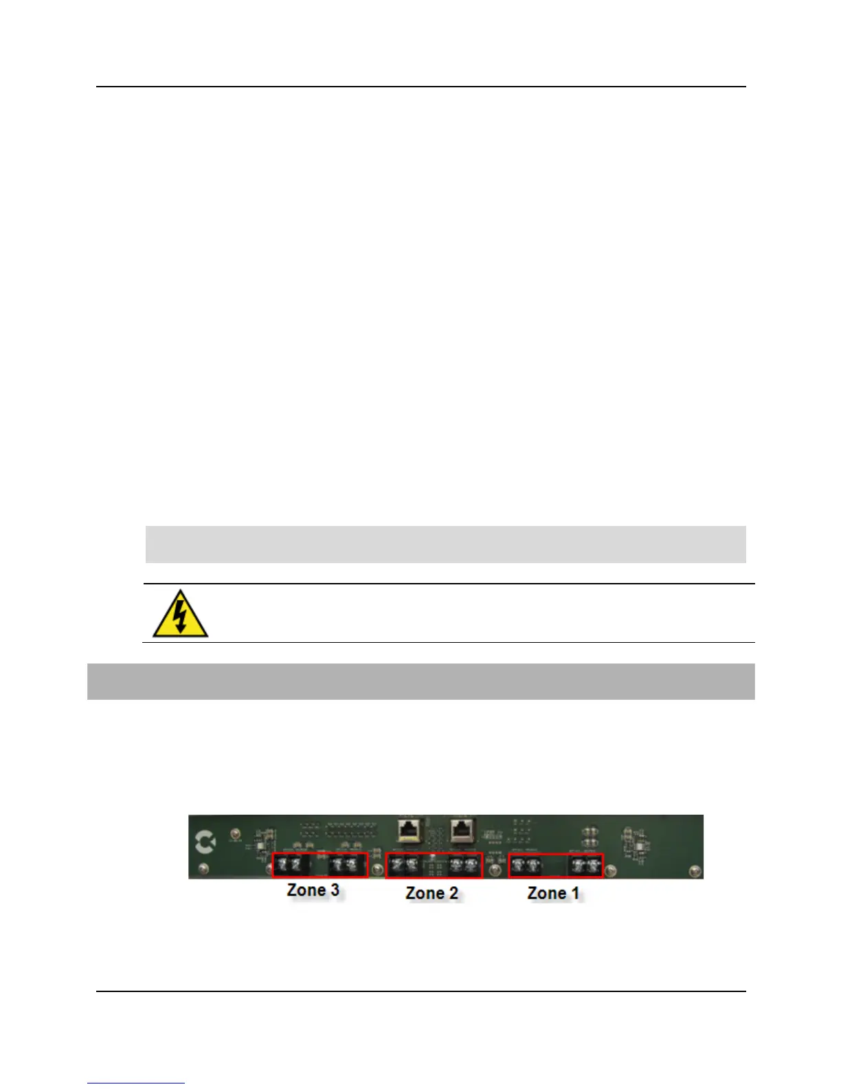
The Calix E7-20 requires -48 VDC input power, which is then split into three power zones.
Each power zone has redundant A and B power terminations available and is connected to a
separate 30-Amp circuit breaker, for a total of six circuit breakers when both A and B feeds
The Calix Circuit Breaker Panel (Calix Part No. 100-00573) provides protected distribution
of power. It consists of two separate circuits, A and B, each of which provides monitored
protection for three redundant power feeds to a single E7-20 shelf. A 30-Amp fuse per
circuit breaker is recommended. An alarm feature allows the Circuit Breaker Panel to provide
a warning if a circuit breaker trips. See the Calix Circuit Breaker Panel datasheet for
The power zones are divided, as follows:
H0K47!P2FF$%43!/0!"0NF0-4-/.!
!! Line cards 9-12, Slots A and B, Fan Tray Assembly
Note: The E7-20 must be installed in an Isolated DC return (DC-I) configuration, where the
DC return is not connected to the grounding system.
MBR1'?\!!*&.T!4C!/%/6-0&6!.,46T(!\5%Q!$!RD$%&C&/2!-/6,5&6&$5!.,4D%2!
C0!I0--4I/!M"!F0K47!/0!/D4!'()*+!
9A! Get the 10-foot DC power cables with A and B leads from the installation kit.
*A! On E7-20 rear panel, loosen the two captive thumbscrews securing the clear plastic
power terminal cover to the chassis, and then remove the cover.
:A! Connect the DC power cable to each power zone ont the E7-20 chassis as follows: