Proprietary*Information:*Not*for*use*or*disclosure*except*by*written*agreement*with*Calix.*
"!#$%&'(!)%%!*&+,-.!*/./01/2(!
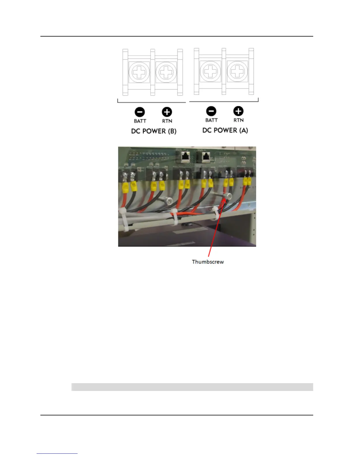
a.! Connect to the A-side power input:
!! Connect the black (A) RTN wire to the (A) + RTN terminal.
!! Connect the red (A) BATT wire to the (A) - BATT terminal.
b.! Connect to the B-side power input:
!! Connect the black (B) RTN wire to the (B) + RTN terminal.
!! Connect the red (B) BATT wire to the (B) - BATT terminal.
c.! Tighten the power termination screws to 17 in-lbs.
<A! Replace the terminal cover and tighten the thumbscrews. Make sure all wires exit cleanly.
The wires can be routed to the left, right, or split with some going in each direction.
EA! Route the power cable to the local DC power source and connect it per local practice.
Note: Use 30-Amp circuit breakers to protect the E7-20 DC distribution circuits.
OA! Power, ground, and alarm wiring at the rear of the E7-20 must be properly secured with