Page 25
OPTIONAL REMOTE SENSOR BOX
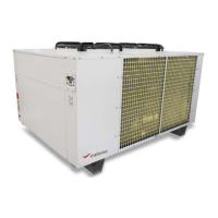
Isolate the Low Speed fan circuit breaker when the remote sensor box is fitted. (Marked FAN L). Position in
electric box shown below. This stops the fan when there is no demand for humidity or air temperature control.
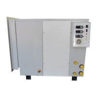
Disconnect wires to sensors at electric box terminals & run leads to sensor box & connect as shown
use 0,5mm² cable up to 20 metres.
12345
P7
P6
P5
P4
P3
THERMOSTAT
HYGROSTAT
P5 P6 P7P4P3P2P1
W 0,5
V 0,5
PU
GR
LB
B
DISCONNECT LEADS THIS SIDE & REPLACE
WITH REMOTE SENSOR LEADS
SENSOR BOX TERM 1
SENSOR BOX TERM 2
SENSOR BOX TERM 3
SENSOR BOX TERM 4
SENSOR BOX TERM 5
P3P2P1 P4 P5 P6 P7
SENSOR/PROBE TB
REMOTE OVERRIDE
SWITCH
REMOTE ON/OF F
(12V)
N L
BOILER
DEMAND
REMOTE POWER
INDICATER (12V)
45
6
7
89
10
11
12
13
14
15
16
17
18
19
20
21
22
23
24
25
26
27
28
29
30
31
SENSOR PLUG AND TERMINAL BLOCK
COMP
FAN H
FAN L
CONT
A1
A2
12
3
4
5
6
21 22
COMP
CONT