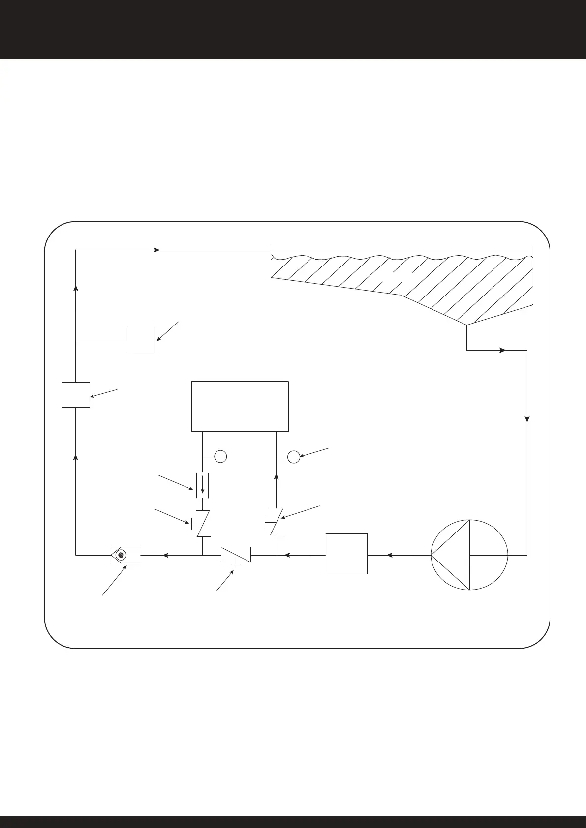
POOL WATER SCHEMATIC
FILTER
FLOW SETTING
PRESSURE GAUGES
METHOD
PUMP
POOL
NON
RETURN
VALVE
SANITISER OR
CHEMICAL DOSING
POSITION AFTER
CALOREX
(STANDARD)
CALOREX
ENSURE POOL FILTRATION PUMP SELECTION ALLOWS FOR ALL SYSTEM RESISTANCE
OR LOOP
FLOW
SETTING
FLOW METER
METHOD
VALVE
VALVE
ISOLATING
B
ISOLATING
A
VALVE C
BYPASS VALVE
(LOCKING GATE VALVE TYPE)
AUX
HEATER
IF FITTED
FLOW METER METHOD (SEE FIG 3.)
Ensure isolation valves ‘A’ and ‘B’ and bypass valve ‘C’ are fully open.
Close e bypass valve until e flow light at is positioned on e
heat pump console illuminates and en close it slightly more to allow
for flow loss due to a dirty filter. Remove handle and lock off valve ‘C’.
Alternatively a water flow meter can be installed. See data sheets for
flow rates.
The Pro-Pac is fitted wi a water flow switch which inhibits e
operation of e machine when e minimum water flow is inadequate.
Adjust e water flow rate rough e heat pump until e green
Water Flow OK lamp on e machine console is illuminated. An
adequate water flow rate has now been achieved.
Fig 3
4. DETERMINING WATER FLOW
10
SD566252 ISSUE 51
PR0-PAC SYSTEM OWNER INSTALLATION MANUAL