37
in.temp prerequisite conditions in.temp prerequisite conditions
• Avoid locating the unit close to bedrooms or other noise sensitive areas.
• Avoid a location that can amplify vibrations (ex. Securing the unit to a wall)
• The fan should not blow towards windows, walls, or spaces inhabited by people or animals
• Do not install this unit where it will be subjected to contaminated or polluted air.
• Avoid directing the in.temp fan against the ow of dominant wind directions, if there is a section of
the property where there is a consistent breeze or an area that tends to collect and gather more tree
leaves than the rest of the property. Avoid placement in these areas to prevent the fan from sucking
in debris or blow debris across the property.
• Protect the heat pump from possible snowfall. If possible ensure that the in.temp is not directly ex-
posed to environmental conditions, and never block the air ow.
• Insulate the external water pipes between the spa and the in.temp with insulation foam.
13
Precautions
• Avoid locating the unit close to bedrooms or other noise sensitive areas.
• Avoid a location which could create vibration (e.g. secured to a solid wall).
• The fan should not blow towards windows, walls or spaces likely to be inhabited by people or animals.
• Do not install where the in.temp is likely to be subjected to polluted air, dust or debris, etc.
• Avoid directing fan output against the dominant wind directions.
• Protect the heat pump from possible snow fall.
• Minimize exposure to environmental conditions as much as possible and never block the airflow.
• Insulate the external water pipe between the spa and the in.temp with insulation foam.
• Install the valves inside the spa skirt to enable winterization.
Securing the in.temp
The in.temp should be securely fixed. The four included rubber mounts should be installed to absorb high-frequency
vibrations.
Piping
A bypass, consisting of three valves, must be installed to adjust water flow to the in.temp and to isolate the apparatus
for maintenance purpose. For a more stable flow in the heat exchanger, it is recommended to install the in.temp on the
pressure side of the main pump.
If your installation is equipped with a water treatment system (chlorine, bromine, salt, etc.) the bypass must be installed
before the water treatment, with a check valve between the bypass and water treatment system.
Installation
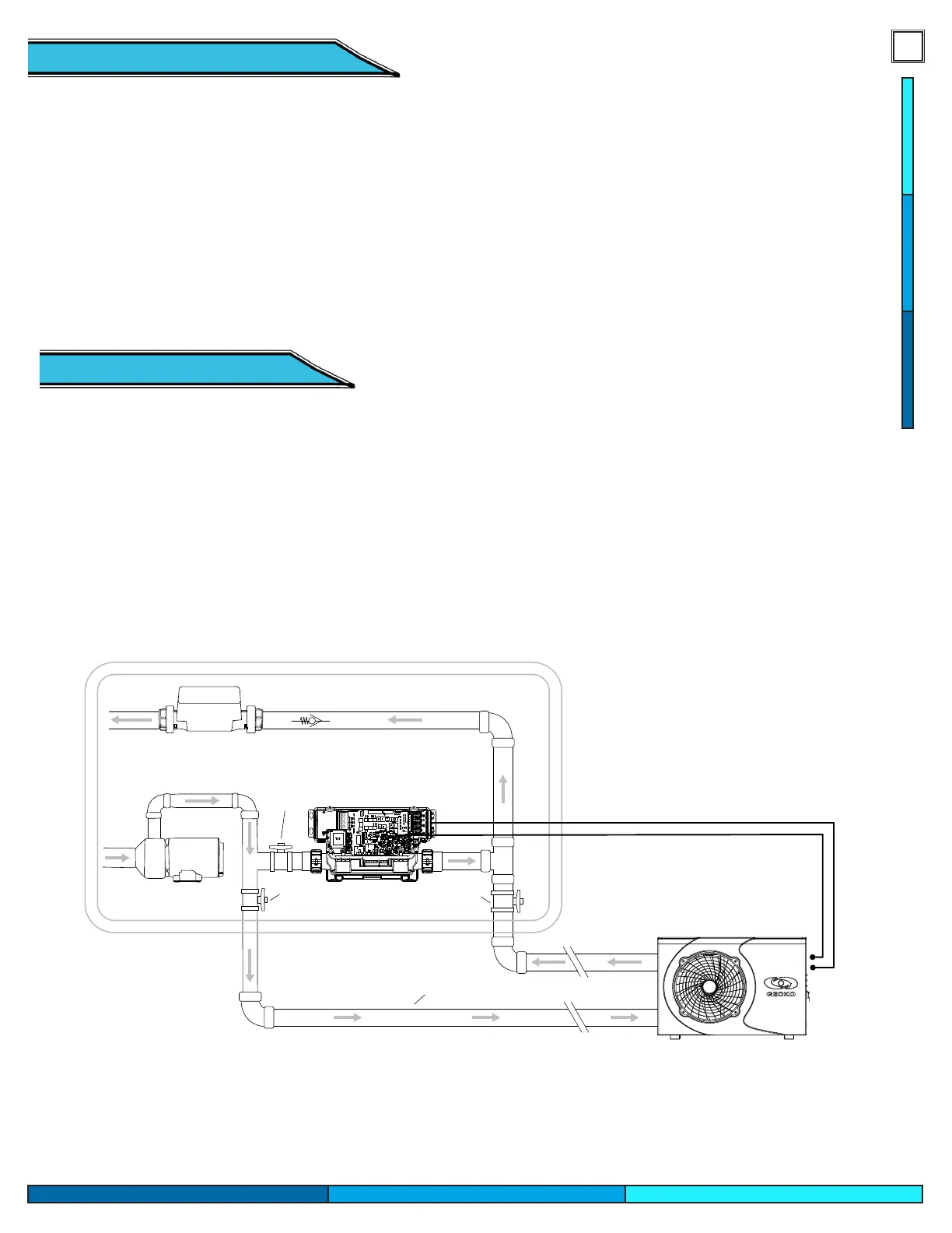
input valve output valve
flow
regulation
In order to limit the heat loss from the piping, it is recommended to install the heat pump
as close as possible to the spa. A 16 foot (5 m) cord is provided.
water in
water out
in.temp
communication port RS485
power in
spa circulation/
main pump
spa control
check valvein.clear
(sanitation)
water in
water out
1.5 in piping to the in.temp
spa equipment bay
in.temp Plumbing Diagram in.temp Plumbing Diagram
If you have requested your Cal Spa to include the in.temp system, certain plumbing ttings will be prein-
stalled inside of your spa. The diagram below is intended to provide insight on how the in.temp system
plumbing should be laid out.
Note: The in.clear (Bromine Generator) is an optional add on selected when ordering your spa.