phn-3962 004v000
Page vii
List of Figures
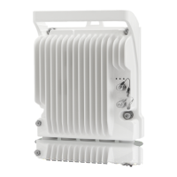
Figure 1 PTP 820C Rear View (Left) and Front View (Right) ................................................................ 2-2
Figure 2 Cable Gland Construction ........................................................................................................ 2-2
Figure 3 PTP 820C Interfaces .................................................................................................................. 2-3
Figure 4 Splitter ....................................................................................................................................... 2-4
Figure 5 OMT ........................................................................................................................................... 2-5
Figure 6 PoE Injector ............................................................................................................................... 2-6
Figure 7 PoE Injector Ports ..................................................................................................................... 2-7
Figure 8 System Components ................................................................................................................ 2-8
Figure 9 Grounding cable ....................................................................................................................... 3-3
Figure 10 Ethernet cable design .......................................................................................................... 3-13
Figure 11 Glands ................................................................................................................................... 3-17
Figure 12 Removing glands ................................................................................................................. 3-18
Figure 13 Transparent Pressure Windows. ............................................................................................ 5-2
Figure 14 MIMO/Protection signaling cable 1..................................................................................... 5-13
Figure 15 MIMO/Protection signaling cable 2..................................................................................... 5-14
Figure 16 MIMO/Protection signaling cable 3..................................................................................... 5-15
Figure 17 MultiCore 2+0 Dual Polarization Remote Mount ................................................................. 6-5
Figure 18 MultiCore 2+0 Single Polarization Remote Mount ............................................................ 6-13
Figure 19 MultiCore 2+2 HSB Double Polarization Direct Mount ..................................................... 6-19
Figure 20 MultiCore 2+2 HSB Double Polarization Remote Mount .................................................. 6-23
Figure 21 MultiCore 2+2 HSB Single Polarization Direct Mount ....................................................... 6-31
Figure 22 MultiCore 2+2 HSB Single Polarization Remote Mount ................................................... 6-36
Figure 23 2 x MultiCore 2+0 Dual Polarization Direct Mount ............................................................ 6-44
Figure 24 2 x MultiCore 2+0 Dual Polarization Remote Mount ......................................................... 6-47
Figure 25 2 x MultiCore 2+0 Single Polarization Direct Mount ......................................................... 6-54
Figure 26 2x2 LoS MIMO Direct Mount ............................................................................................... 6-57
Figure 27 2x2 LoS MIMO Remote Mount ............................................................................................ 6-62
Figure 28 4x4 Los MIMO Direct Mount ................................................................................................ 6-67
Figure 29 2+2 HSB Single Polarization Remote Mount ..................................................................... 6-78
 Loading...