Do you have a question about the CAME BX-78 and is the answer not in the manual?
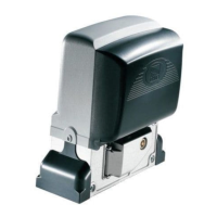
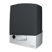
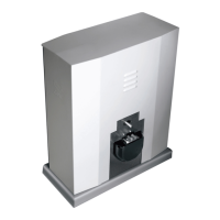
Describes the purpose of the BX-74/BX-78 motors.
Lists the maximum gate weight limitations for BX-74 and BX-78.
Details the construction and warranty of the operator.
Lists technical specifications for BX-74 and BX-78 operators.
Lists essential checks before starting the installation process.
Explains the control board's power supply and functions.
Identifies and lists the main components of the control board.
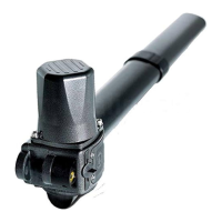
Details connecting the antenna to the radio frequency card.
Lists various CAME remote control transmitter models.
Outlines routine maintenance tasks for the end-user.
Provides a table of common malfunctions, causes, and remedies.
This document describes the CAME BX-74 and BX-78 automation systems for sliding gates, providing installation, safety, and maintenance instructions.
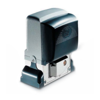
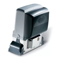
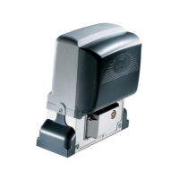
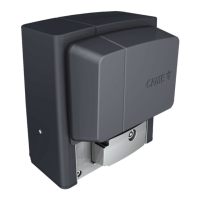
The BX-74 motor is designed for residential sliding gates, while the BX-78 can also be used in condominiums. These operators are engineered and manufactured by CAME CANCELLI AUTOMATICI S.p.A. in compliance with current safety standards, holding ISO 9001:2000 quality certification and ISO 14001 environmental safeguarding certification. The operator consists of a cast aluminum part housing an irreversible, electromechanical gearmotor, and an ABS plastic lining that holds the electronic card and transformer. It is crucial to use CAME original command, safety equipment, and accessories to ensure proper operation and maintenance.
Installation must be carried out by expert qualified personnel in full compliance with current regulations. Before installation, several preliminary checks are necessary: ensuring the gate is stable with well-greased castors, verifying the ground rack is securely fixed, entirely above the surface, and free of obstructions. The upper guide rails must not create friction, and there must be both closing and opening endstops. The operator must be attached to a solid surface and protected from impacts. A suitable omnipolar cut-off device with contacts more than 3 mm apart and an independent power supply are required. Connections inside the container that provide continuity to the safety circuit must have additional insulation. Proper tubing and conduits for electrical cables are essential to protect them from mechanical damage.
The installation process involves securing a mounting plate by digging a pit next to the gate, preparing corrugated tubes for electrical connections, and inserting a form box that extends 50mm above ground level. An iron grid is placed inside the form box for concrete reinforcement. The securing plate is then prepared by inserting bolts and locking them with nuts and washers, and preformed brackets are extracted. The plate is positioned on top of the grid, ensuring the tubes pass through the appropriate holes. The form box is filled with cement, and after waiting at least 24 hours for it to solidify, the form box is removed, and the pit is filled with soil. The nuts and washers are unbolted, and the securing plate must be clean, perfectly aligned, with bolt threads completely on the surface. Electrical cables are inserted into the tubes until they exit about 400mm.
To install the gearmotor, the cover is removed by loosening side bolts, cable shafts are perforated, and the gearmotor is placed atop the plate, ensuring electric cables pass through the shafts. The gearmotor is then lifted 5 to 10mm from the securing plate using threaded steel-leveling feet to allow for later adjustments between the pinion and the rack. The rack is secured by releasing the gearmotor, resting the rack on the gearmotor pinion, and welding or securing it to the gate along its entire length. For assembling rack modules, an excess piece of rack is placed under the joining point and blocked with C-clamps. If a rack is already in place, only the pinion-to-rack distance needs adjustment. The gate is manually opened and closed to register the pinion-to-rack distance using the threaded steel-leveling feet for vertical adjustment and slotted holes for horizontal adjustment, preventing the gate's weight from bearing on the operator. After adjustments, the assembly is secured with nuts and washers, and the cover is inserted after electronic card settings. Endstop fins are placed on the rack and secured with a 3 mm Allen wrench to limit gate travel, ensuring the gate does not slam against mechanical stops.
Manual release of the gearmotor is achieved by inserting the trilobed key into the lock, pushing it in, and turning it clockwise. Then, the small door is opened, and the release handle is turned clockwise. A warning indicates that opening the door disengages the motor, and the release mechanism must be firmly fastened for motor operation.
The control board operates on 230V A.C. for the electronic card and 24V for command devices and accessories, with a maximum accessory power of 20W. Photocell functions include re-opening during closing, partial stop, total stop, and obstacle detection when the motor is stopped. If a normally closed safety contact is opened, a signaling LED flashes. The optical reader inverts the gate's direction upon obstacle detection during opening or closing. After three obstacle detections, the gate stops in opening mode, and automatic closing is excluded, requiring a command button or remote control to resume movement. All connections are fuse-protected. The card handles automatic closing, warning light pre-flashing, and obstacle detection. Command modes include opening/closing, opening/closing in maintained action, partial opening, and total stop. Trimmers regulate automatic closing time and partial opening time.
Programming decelerations involves setting all DIP SWITCHES to OFF, then setting specific DIP Switches (4, 7, 8, 9) to ON and DIP Switch 3 to OFF. Pressing CH1 until the red LED flashes (about 3 seconds) initiates a full open and close cycle. Once the LED stays on, programming is complete, and DIP SWITCHES are reset to previous settings. The decelerated gate speed can be adjusted by pressing CH1 (to reduce) or CH2 (to increase) during deceleration. If power is cut during gate closure with decelerations active, the operator performs a full, decelerated opening and closing cycle upon power restoration. The re-closing partial stop function during opening can be modified by setting DIP Switches 1 and 4 to ON, pressing CH1 until the red LED flashes and then stays lit (about 5 seconds), and then resetting DIP SWITCHES. Pressing CH2 reverts to the default selection.
Motor torque can be adjusted by moving a faston with a black wire to one of four positions (1 min – 4 max). Radio command activation involves inserting the radio frequency card into the electronic card after disconnecting power. The antenna's RG58 cable is connected to the appropriate terminals. Transmitters are memorized by pressing the CH1 button on the electronic card until the LED flashes, then pressing the desired transmitter button. The LED will stay on to confirm memorization. The CH2 button can be associated with another transmitter button for auxiliary devices or controlling two paired motors.
For connecting two joined motors with a single command, the direction of travel for both motors must be coordinated by modifying motor B's rotation. Electrical connections are made on motor A's command card. Both cards must have the same settings and activated functions (Dip Switches). Connections between the two command cards are made as per the provided diagram, noting that the (2-3P) partial opening button connects to the command card's terminal board of the motor in question (motor A for left-opening, motor B for right-opening). The AF radio card is inserted into motor A's command card, and the radio command is activated using the CH2 channel. After memorizing the code, contacts B1 and B2 are connected to contacts 2 and 7, and the command type is selected on both cards using Dip-Switches 2 and 3.
Safety instructions emphasize that the product must only be used for its intended purpose. Working near hinges or moving parts, or being in the opening/closing arc during operation, should be avoided. Force should not be applied against the operator's motion. Children should not play near the operator, and remote controls must be kept out of their reach. In case of anomalous behavior, the operator should be stopped immediately. Warnings include danger of crushing hands or feet, high voltage, and no transit during operation.
Periodic maintenance for the end-user (every 6 months) includes cleaning photocell glass, checking safety device functionality, removing obstructions, and checking lubrication and anchoring screw tightness. To test safety devices, an object is moved in front of photocells during closing; if the operator inverts motion or stops, the photocells are working. Maintenance requiring power disconnection should be performed by professionals. Photocell cleaning should be done with a damp cloth, avoiding solvents. Strange vibrations or squeaking indicate a need to lubricate joints. Plants must be kept clear of the photocell beam, and gate motion must be unobstructed.
Troubleshooting guidance is provided for common issues: if the gate does not open or close, possible causes include no power, gearmotor in release mode, dead transmitter batteries, broken transmitter, stuck stop button, stuck opening/closing button, or photocells in partial stop mode. Remedies include checking power, calling assistance, replacing batteries, or checking photocells. If the gate opens but won't close, engaged photocells are a likely cause, requiring cleaning or assistance. If the gate closes but won't open, a triggered sensitive edge is a possibility. If the flasher doesn't work, the bulb may be burnt. A log is provided for both periodic and extraordinary maintenance, with sections for installer and operator details, job date, and signatures.
Disposal instructions emphasize CAME's environmental protection system. Packing materials (cardboard, plastic) are solid urban waste and can be recycled after separation. Product components (aluminum, plastic, iron, electric cables) are mostly solid urban waste and can be recycled by authorized firms. Other components (electrical circuit board, remote control batteries) may contain hazardous waste and must be disposed of by licensed firms. Local laws should always be checked before disposal. The document concludes with a manufacturer's declaration of conformity, stating compliance with European Directives and Standards.
| Max Gate Weight | 800 kg |
|---|---|
| Operating Temperature | -20°C to +55°C |
| Power Supply | 230V AC |
| Voltage | 230V AC |
| Safety | Safety Edges |
| Manual Release | Yes |