3 12/2016 © CAME S.p.A. - The data and information reported in this installation manual are susceptible to change at any time and without obligation on CAME S.p.A. to notify users.
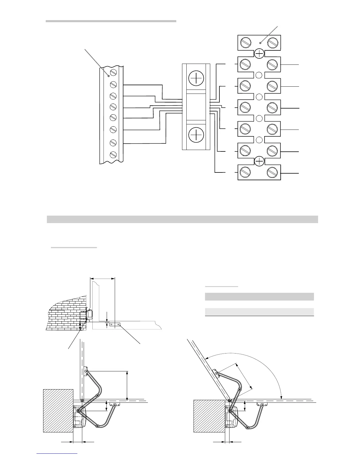
Connecting to the ZL19N/ZL170N control panel
M -N
Connecting the motor
F -Fa
Opening endstop microswitch
R -Rc
Closing-speed brake microswitch
Motor 1: C-Rc1-Fa1-C-M1-N1
Motor 2: C-Rc2-Fa2-C-M2-N2
Motor terminals
Control panel terminal board
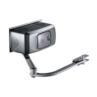
Securing the brackets
N.B. the drawings refer to installation of the left-hand gearmotor. The installation of the right-hand gearmotor is symmetrical.
Determine the fixing point for the gate bracket and calculate the fixing point of the pillar bracket, respecting the values shown in the drawings and table.
Gate bracket
Pillar bracket
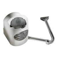
INSTALLING AND CONNECTIONS FOR OUTWARD-OPENINGS
Below are the only procedures that vary compared to standard installations:
Application size
Leaf opening A B
90° 150
0 120
120° 150
0 60