0.2 03/2010
© CAME cancelli automatici s.p.a. -
The data and information reported in this installation manual are susceptible to change at any time and without obligation on CAME cancelli automatici s.p.a. to notify users.
ENGLISH
N.B.: An evaluation of the size of the cables with lengths other than the data in the table must be made based on the eff ective absorption of the connected devices,
according to the instructions indicated by the CEI EN 60204-1 standards.
For connections that require several loads on the same line (sequential), the size given on the table must be re-evaluated based on actual absorption and distances.
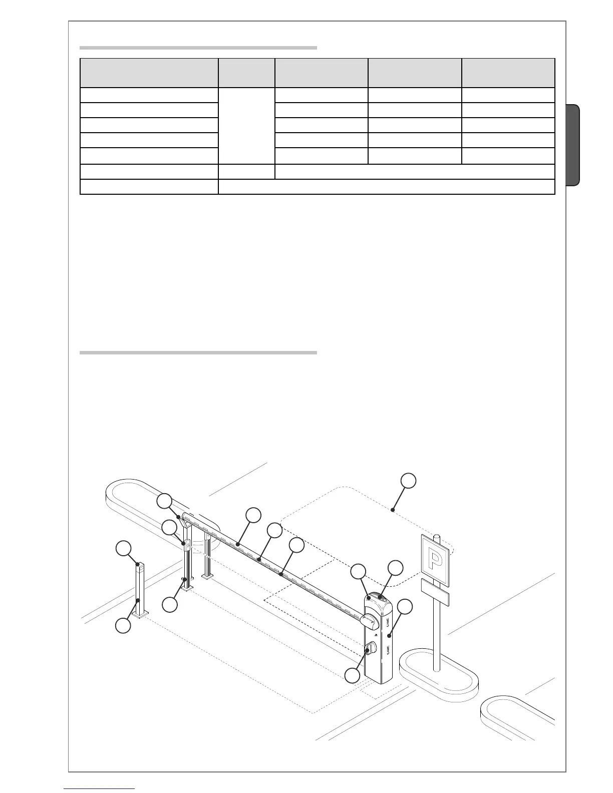
1 - GARD unit
2 - Control panel
3 - Aluminium bar
4 - Red phosphorescent strips
5 - Luminous cord
6 - Movement-indicating flashing lamp
7 - Column for photoelectric cells
8 - Photoelectric cells
9 - Fixed barrier support
10 - Magnetic sensor
11 - Photoelectric cell support
12 - Magnetic reader
13 - Column for reader
5.3 Cable list and minimun thickness
5.4 Standar installation
Connections Type of cable
Length of cable
1 < 10 m
Length of cable
10 < 20 m
Length of cable
20 < 30 m
230V 2F power supply
FROR CEI 20-22
CEI EN
50267-2-1
3G x 1,5 mm
2
3G x 2,5 mm
2
3G x 4 mm
2
Photoelectric cells TX 2 x 0,5 mm
2
2 x 0.5 mm
2
2 x 0,5 mm
2
Photoelectric cells RX 4 x 0,5 mm
2
4 x 0,5 mm
2
4 x 0,5 mm
2
24V power supply accessory 2 x 0,5 mm
2
2 x 0,5 mm
2
2 x 1 mm
2
Safety and control divices 2 x 0,5 mm
2
2 x 0,5 mm
2
2 x 0,5 mm
2
Antenna connection RG58 max. 10m
Metallic mass detector (see documents provided with product)
 Loading...


