- pag. - pag.
- pag. - pag.
- pag.
99
99
9
- english - - english -
- english - - english -
- english -
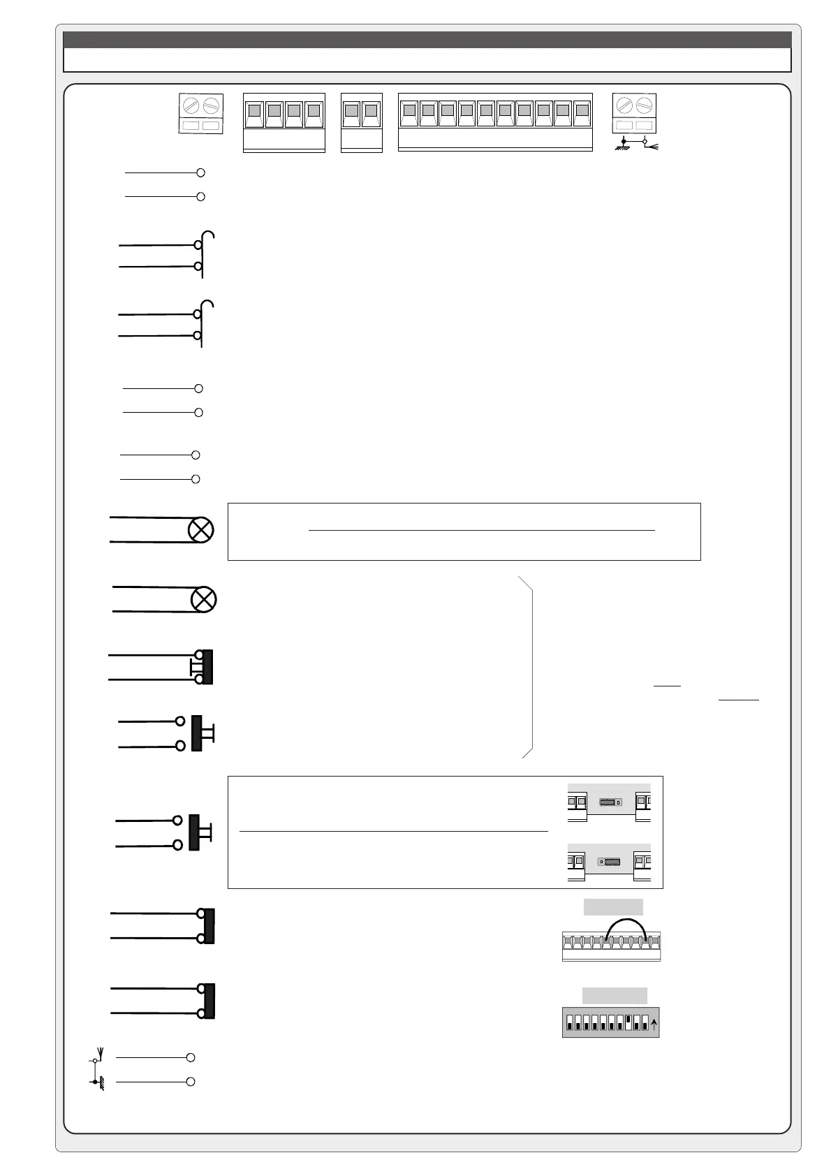
ALLACCIAMENTI & REGOLAZIONI ELETTRONICHE
QUADRO ELETTRICO ZL37B
L1 L2
FA FC F PT
E+10 - 11 1 2 C 1 C 5735
F
FA
F
FC
M
N
24V A.C. motor
Connection limit switch deceleration opens
Connection limit switch deceleration closes
230V A.C. power
Accessory power: 24V A.C. max. 40W
24V output
24V - 3W max. "barrier open" warning light
STOP button (N.C.)
(see selection functions)
OPEN button (N.O.)
Connector (N.O.) radio and/or pushbutton.
See DIP 2 for command type
Button operation: closure only
Contact (N.C.) for re-opening during closure, if not
used ....
Contact (N.C.) of immediate closure, if not used ....
Antenna connection
L1
L2
10
5
10
E
10
11
1
2
2
3
2
7
2
C5
2
C1
E 10 111 2 3 5 7C
1
C
5
2-C1
!"
#
$%
&'
ON
dip 8 ON
DIP 3 OFF
DIP 3 ON
during movement (e.g. flashing light)
during movement and in the closed position
74
74
jumper n°8
To install additional pushbutton arrays,
connect:
- the stop buttons in
serie
- the open and warning light in parallel

 Loading...