4.0 03/2009 © CAME cancelli automatici s.p.a. - The data and information reported in this installation manual are susceptible to change at any time and without obligation on CAME cancelli automatici s.p.a. to notify users.
ENGLISH
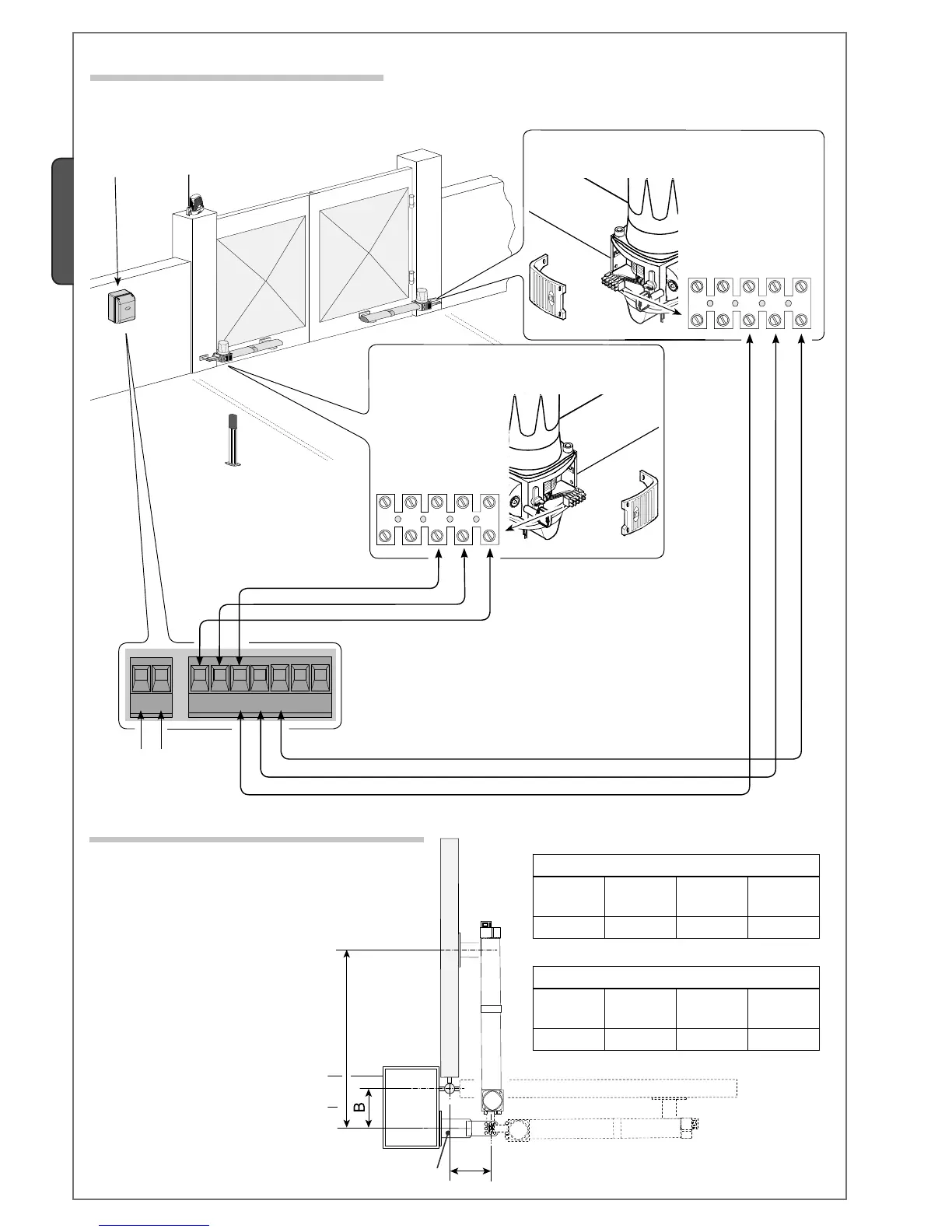
For the electrical connection procedures, use the junction box and branching boxes.
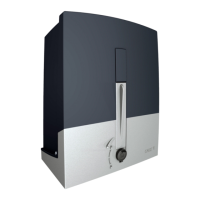
5.6 Connecting to the control panel
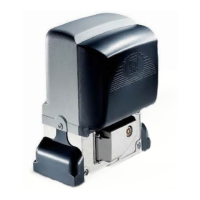
ZA3N / ZM3E Control panel
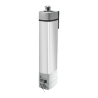
Connecting the 230V a.c. delayed opening
gearmotor.
Connecting the 230V a.c. delayed closing gearmotor.
Power supply
230V a.c. - 50/60 Hz
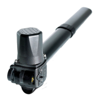
5.7 Outward opening installation
Gate leaves up to 3 m (KR3)
Opening
A
(mm)
B
(mm)
E
(mm)
90° 130 130 910
Weld the extra bracket to that of the pillar,
secure the extra bracket to the pillar
making sure the A and B quotas are met
as shown in the table.
Open the gate to a 90° arc, weld or
secure using proper screws the gate
bracket making sure the E quota is met.
Secure the gearmotor to the brackets.
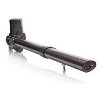
Gate leaves up to 5 m (KR5)
Opening
A
(mm)
B
(mm)
E
(mm)
90° 130 130 1310
Extra bracket