1
2
3
4
5
16
14
15
11
12
6
9
10
7
8
13
17
18
p. 14 - Manual FA01084-EN - 02/2018 - © CAME S.p.A. - "Translated original instructions"
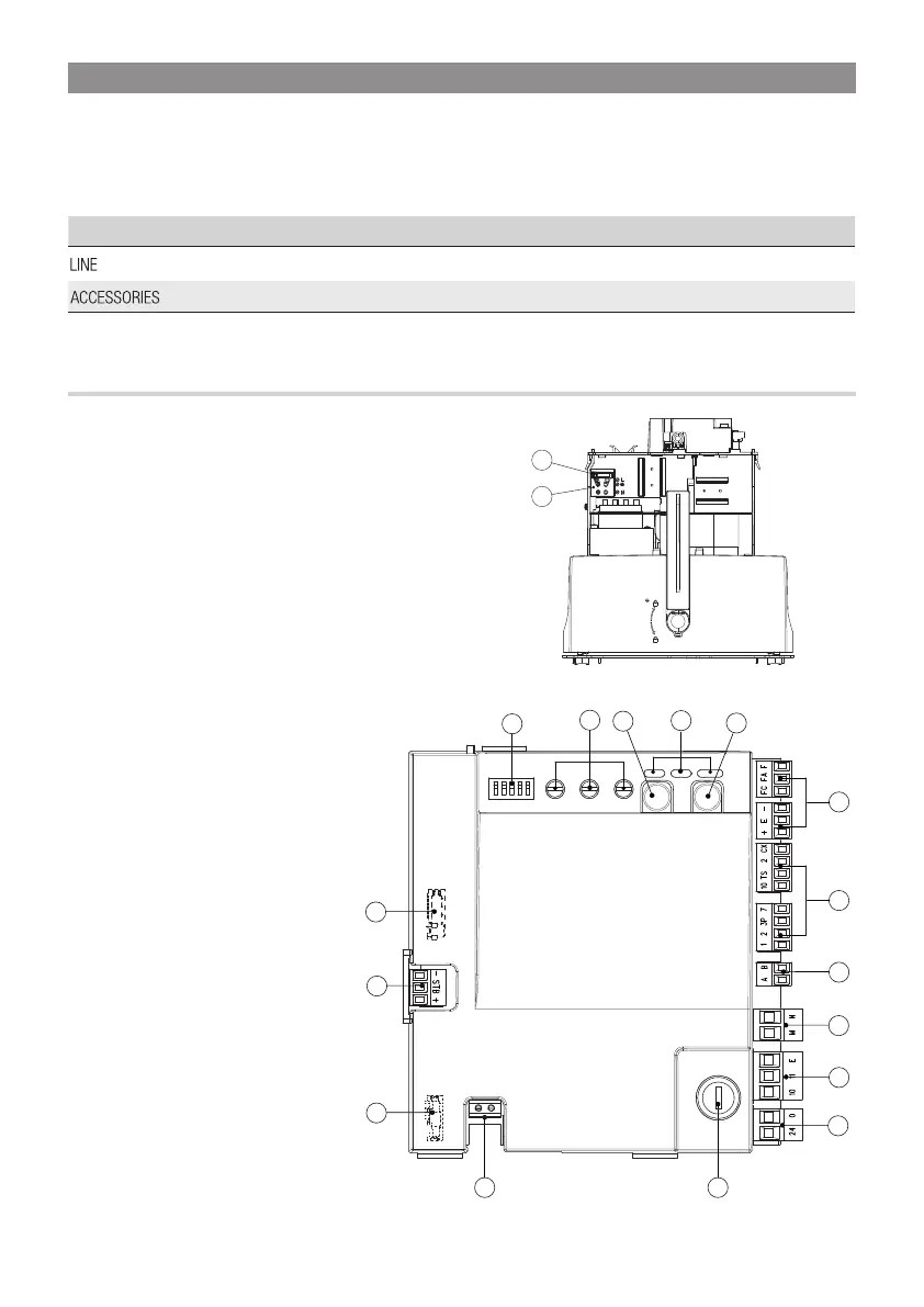
DESCRIPTION OF PARTS
1. DIP-SWITCH
2. Trimmer
3. Programming button
4. Alert LED
5. Button Button (7)
6. Encoder and endstop terminals
7. Command and safety devices terminals
8. Keypad selector terminal
9. Terminal for gearmotors
10. Power supply to accessories terminal
11. Power supply to control board terminal
12. Accessories / board fuse
13. Antenna terminal
14. AF card slot
15. Green power module terminal
16. R800 card connector
17. Power supply terminal board
18. Line fuse
ELECTRICAL CONNECTIONS AND PROGRAMMING
⚠
Caution! Before working on the control panel, cut off the mains power supply and remove any batteries.
Powering up the control board and command and control devices: 24 V AC/DC.
⚠
Careful! The accessories connected onto 10-11 must never exceed 20 W overall.
Use DIP switches to set functions and the trimmer for adjustments.
All wiring connections are quick-fuse protected.
Fuses
ZN6
- Line 1.6 A-F
- Accessories 2 A-F