ENGINEERED & PROCESS VALVES
01/2011 / IOM-TK-TMBV-01
19
Installation, Operation and Maintenance Manual
8. Remove one seat from the closure and the other from the body. Gently tapping from
underneath the seat will allow the seats to become free.
9. Collect and retain springs.
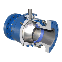
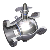
Three-Piece Trunnion Supported
4. Remove both closures. One seat will come out with each closure.
5. Remove the seats from the adapters by using a jack screw and lifting straight out.
6. Collect and retain springs.
7. Position valve, without closures, such that the stem and trunnion are in the horizontal positions
and apply support for ball.
8. Remove bonnet, stem, and trunnion from sub assembly. By lifting the ball to relieve pressure
from the stem and trunnion, it is then possible to remove the stem and trunnion.
9. Carefully remove ball from body cavity once the stem and trunnion have been removed.
Continue Disassembly for all Valve Designs
10. The bonnet bore, thru which the stem passes, is a sealing surface. Before removing the stem
from the bonnet, dress the exposed portion of the stem by remove all rust, nicks, burrs, ect and
spray with penetration oil. Then gently tap the stem out of the bonnet. Do not use a
hard-face hammer!
11. For all valve designs, inspect the bushing in the body bonnet bore. If damaged or worn, replace
before reassembly.
12. Remove all O-rings and replace if necessary. Retain the thrust washer and disc.
Inspection Areas
1. Inspect the surface of the ball for gouges, nicks, pits or other departures on the spherical surface
and particularly in the seating area.
Small isolated imperfections that are less that 1/16” (1.55mm) may be dressed with a light
application of a fine emery cloth.
2. Any gouges, nicks, cuts or thermal distress on the seat sealing area indicates a new seat assembly
is required. Seat assemblies are not field repairable.
3. Stem and ball bushings, washers, and disc should be replaced if damaged or worn.
4. O-rings should be replaced if broken, nicked, frayed, stretched, or swollen. If O-rings are dam-
aged due to incompatible service conditions, consult with the nearest representative
or the factory.