ENGINEERED & PROCESS VALVES
14
01/2011 / IOM-TK-TMBV-01
Installation, Operation and Maintenance Manual
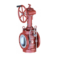
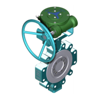
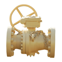
MOUNTING A GEAR BOX/ACTUATOR
Scope
To establish work instructions for the mounting and setting the stop sequence for the gear operators,
thereby assuring that the proper installation practices are followed on all valves.
Mounting and Setting Stops
With the operator positioned with the cover down, install the mounting studs. Measure the bonnet and
operator nut thickness to gage the proper amount of stud to leave protruding from the gearbox.
Spray the face of the valve bonnet with spray grease. If the valve is sub-sea use flange sealant in place of
the spray grease.
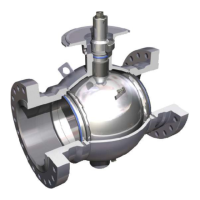
Before sliding the operator completely against the bonnet, check the position of the handwheel shaft,
which should point to the side away from the bleed valve on three piece OF valves. On two piece OF
valves,
the shaft will be to the bottom right. The shaft will always be at 90 degrees from the centerline of
the valve and never at an angle. The operator can be rotated around the stem into the proper position,
without removing it from the stem.
After correctly positioning the handwheel shaft, slide the operator toward the bonnet placing the studs
through the bonnet flange until approximately 1/4” of the stud is exposed on the back of the flange.
Start all nuts onto the studs (flat side down) and tighten them with the proper open end wrench.
Remove the indicator plate from the top of the operator. Using the handwheel, turn the operator so
that the keyslot of the stem and operator are aligned with each other. On small gearboxes, it is possible
to install the key on the stem prior to sliding the operator onto the valve shaft.
Install the square key into keyslot until it is below the surface of the operator hub. Do not use excessive
force to drive the key! If the key does not fit properly, recheck the alignment of the slots. (Another key
or pin punch should be used to drive against the key to prevent damage to the operator key or key slot).
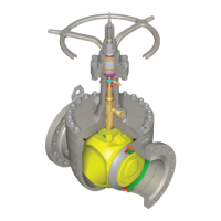
To set the closed stop, turn the handwheel clockwise until the key slot in the valve stem is at a 90 degree
angle to the valve flow bore. Loosen the jam nut on the stop farthest from the handwheel shaft (see
illustration). Then turn the stop bolt clockwise until it stops. Retighten the jam nut. It may be necessary
to turn the stop screw counter clockwise in order to get additional travel and move the operator farther
closed. The handwheel should always be turning in the closed direction to set the closed stop so that all
slack will be taken out of the gearing. This ensures a more accurate stop setting.
After setting the closed stop, a check should be made to ensure that it has been correctly set. This is
accomplished by turning the handwheel shaft several turns towards the open position, and then
returning it until the closed stop is contacted. The keyway will be at a 90 degree angle to the flowbore.
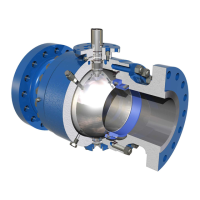
To set the open stop, turn the handwheel shaft counter clockwise until the key slot in the valve stem is
aligned with the valve flow bore. Look into the bore of the valve, and continue opening until the flow
bore of the ball is in alignment with the flow bore of the seatholders. There should not be more than
1/16” of the ball radius exposed into the flow bore once the final setting has been made.