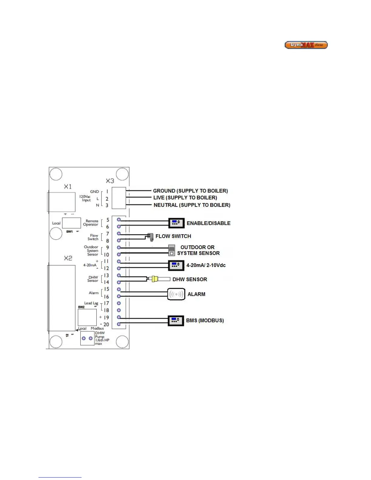
15.2 FIELD WIRING
All wires being placed into the terminal block should be horizontal for at least an inch to ensure sufficient electrical conductivity.
15.2.1 System Sensor
The temperature of the primary return can be controlled by installing a system sensor. The system sensor must be used in all
lead lag modes, and must be enabled through the DynaMax HS controller.
15.2.2 Lead Lag Setup
To setup a lead lag system a master boiler must be chosen, and the other boilers connected to it in this system are designated
as slaves through sequential Modbus addresses.
Connect the system sensor to the master boiler. The master boiler will use the water temperature in the primary loop to control
the operation of the lead lag setup.
If outdoor reset is desired, the outdoor sensor needs to be connected to the Outdoor Sensor location on the DynaMax HS
terminal board on boiler 2 (B-2). If the outdoor sensor is not connected to the Master boiler the DynaMax HS Controller will
maintain a fixed water temperature that is programmed into the control.
If a remote enable signal is available, it needs to be connected to the Remote Operator terminals on the DynaMax HS terminal
board. If the boiler is required to run continuously the switch can be placed in the ‘Local’ position.
 Loading...