Gas burning appliances are divided into four categories based
on the pressure and temperature produced in the exhaust stack
and the likelihood of condensate production in the vent.
Category I. An appliance operating with a non-positive vent
static pressure and with a vent gas temperature that avoids
excessive condensate production in the vent (i.e. “B Vent”).
Category II. An appliance operating with a non-positive vent
static pressure and with a vent gas temperature that may
cause excessive condensate production in the vent.
Category III. An appliance operating with a positive vent
pressure and with a vent gas temperature that avoids
excessive condensate production in the vent.
Category IV. An appliance operating with a positive vent
pressure and with a vent gas temperature that may cause
excessive condensate production in the vent (i.e. “BH Special
Gas Vent”).
The VTech water heater can be vented as either a Category II or
IV appliance. It must be vented and supplied with combustion
and ventilation air as described in this section. Provisions for
combustion and ventilation air are to be in accordance with the
section “Air for Combustion and Installation”, of the National
Fuel Gas Code, ANSI Z223.1/NFPA 54, or clause 8.2, 8.3, 8.4
of “Natural Gas and Propane Installation Code”, CSA
B149.1-15 and CSA B149.2-15, or appliance provisions of the
local building codes. The distance of the vent terminal from
adjacent buildings, windows that open and building openings
must comply with the latest edition of the National Fuel Gas
Code, ANSI Z223.1. In Canada, the installation and clearances
must comply with the latest edition of CSA B149.1-15 and CSA
B149.2-15 Installation Code for Gas Burning Appliances and
Equipment.
For indoor installations, venting must be in accordance with Part
7 “Venting of Equipment” of the National Fuel Gas Code,
ANSI Z223.1, or Section 7 “Venting of Equipment and Air
Supply for Appliances” of the CSA B149.1-15 and CSA
B149.2-15 installation code, or applicable provisions of the local
building codes. Horizontal runs of vent pipe shall be securely
supported (approximately every 4 feet) to prevent sagging and
maintain a minimum slope of ¼" per foot to provide drainage of
the vent towards the nearest drain or the vent termination.
The weight of the venting system must not rest on the unit.
Adequate support of the venting system must be provided in
compliance with local codes and other applicable codes. Vent
connection is made directly to the flue outlet opening on the back
of the unit. All connections should be secured and sealed per the
vent manufacturers specifications. When a positive vent system
is disconnected for any reason, the flue must be reassembled
and resealed according to the vent manufacturer’s instructions.
Do not use an existing chimney as a raceway if another appliance
or fireplace is vented through the chimney.
3.1.1 – Venting Transition
All VTech have a round stainless steel vent connection suitable
for direct connection to PVC or CPVC piping, of the size listed in
Section 1.3.3.
Adaptors for stainless steel venting are available from CAMUS.
Polypropylene vent adaptors are available from the venting
manufacturer directly.
Depending on the venting category chosen and the design
provide by the vent manufacturer, an increaser may be required
for the proper vent configuration.
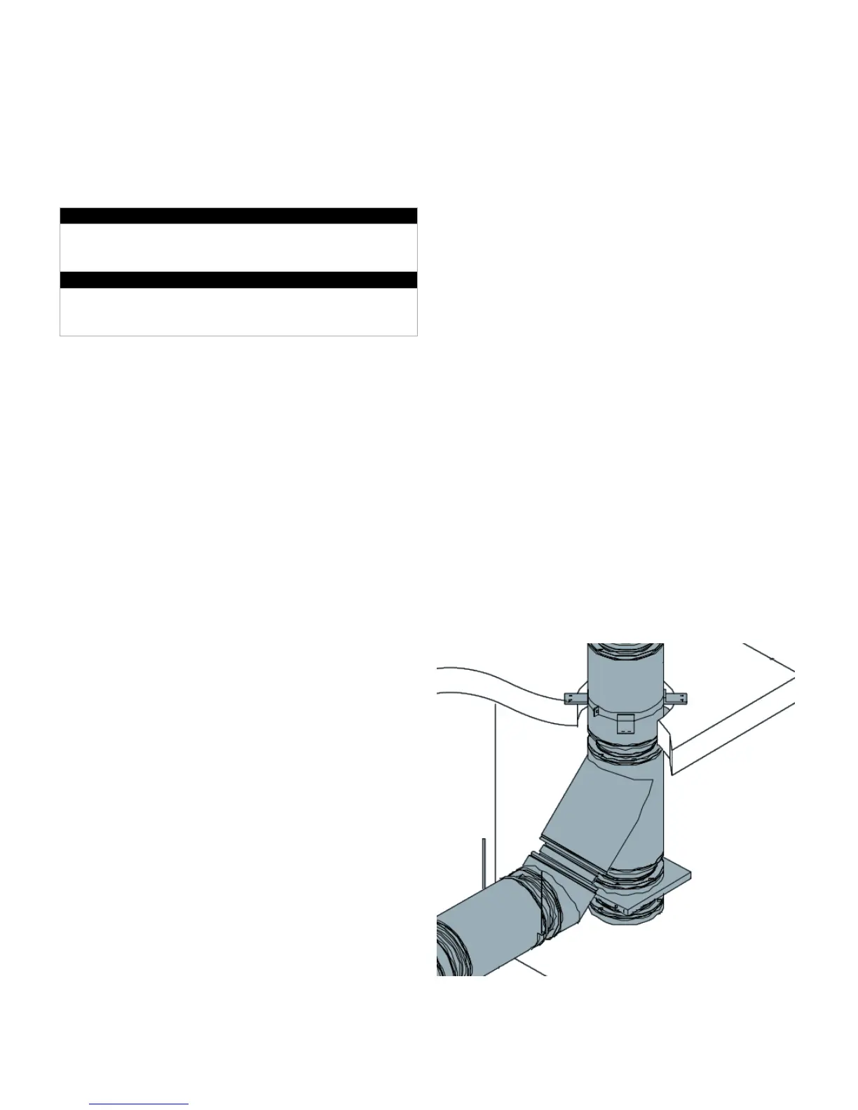
3.1.2 – Vent Drainage
Care must be taken to properly seal all joints against leakage of
exhaust or condensate. All horizontal runs should be provided
with a slope or ¼” per linear foot to ensure efficient drainage of
condensate. This slope should be designed to take condensate
away from the water heater, and towards the nearest vent drain.
The bottom of any vertical vent run should have a combination
45° tee/elbow with drain cap installed to remove condensate in
this area of the vent. If this vertical run includes several horizontal
or angled offsets, all components must be arranged to provide a
continuous downward slope to the tee at the base of the run.
Horizontal sections from this tee must be sloped away, either to
the next tee in the system, or back to the water heater.
NOTE: Any drain in the venting system will require a trap to
ensure flue gas does not enter the interior space.
Combination Tee and Elbow, w/ Drain Cap
In systems where the vent remains horizontal after the initial
vertical rise from the water heater vent connection, it should be
sloped to drain through the sidewall. In cases where the