8
condensate cannot be drained outside, a horizontal drain section
should be installed in the venting before penetrating the sidewall.
The water heater connects directly to a vertical vent run and does
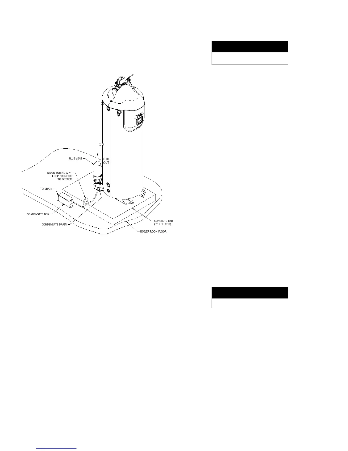
not require a base tee. A drain line must be connected to the
water heater to collect and dispose of condensate.
Drain and Neutralizer Cartridge Installation
Plastic drain tubing shall be provided as a drain line for the water
heater condensate drain. The tubing must have a trap (a 4"
(10cm) diameter circular trap loop in the drain tubing is sufficient).
Prime the trap loop by pouring a small quantity of water into the
drain hose before assembly to the water heater connection. Use
caution not to collapse or restrict the condensate drain line. The
drain must be routed to the condensate neutralization system or
a suitable drain for disposal of condensate that occurs in both the
water heater and in the vent system. Ensure that the drain from
the condensate tee is not exposed to freezing temperature.
3.1.3 – CAT II Venting
A Category II venting system operates with a negative pressure
in the vent at all times, and with flue gas temperatures
sufficiently cool for condensation to occur before reaching the
termination. As a result, a corrosion resistant stainless steel,
such as AL29-4C or 316L, must be used for the venting. AL29-
4C is typically recommended for having higher corrosion
resistance. (This recommendation does not supersede local
codes or the provisions of CSA B149.1-15 and CSA B149.2-
15 in Canada or the National Fuel Gas Code in the United
States.) 316L is limited to use in applications where there is no
possibility of contaminants in the air such as refrigerants, chlorine
etc. Always choose the venting system which best satisfies the
requirements of the application.
The Category II vent systems can be used for single appliances,
but they can also be used to vent multiple appliances combined
into a common vent. This special venting system must be
engineered by a venting manufacturer or other qualified
professional, using a proven vent-sizing program with
knowledge of accurate operating parameters. Approval of the
installation is at the discretion of the authority having jurisdiction.
Acceptable Breech Pressure
For CAT. II Vent Systems
For Category II vent systems, the pressure at the appliance
breeching must be kept within a range of ˗0.05” WC to ˗0.15”
WC. If the calculated draft at any unit exceeds this range (i.e. ≤
˗0.16” WC), a single acting barometric damper, or suitable
alternative draft control approved by the vent designer or
engineer, must be used to prevent the extra suction from
decreasing the pressure at the breeching.
If the vent cannot support a negative draft under all conditions,
and a positive pressure will be developed during some operation,
then the vent design must be changed accordingly. Possible
options include changing the design to Category IV, or providing
an extractor (or “draft inducer”) at the vent outlet, interlocked with
the appliance operating circuit, in order to maintain a negative
draft in the vent while the unit is operating. The designer must
ensure that the solution utilized will maintain the vent system at
the desired minimum draft under all conditions.
Category II vents typically terminate vertically through the roof.
The flue from a Category II vent system must have a condensate
drain with provisions to properly collect, neutralize and dispose
of any condensate that may occur.
3.1.4 – CAT IV Venting
The Category IV venting system operates with positive pressure
at the appliance breeching generated by the combustion air fan,
which operates the combustion process and also exhausts the
flue products from the building. The pressure may be positive
throughout, though it is conceivable to operate with negative
pressure in part of a Category IV vent system. In either case, the
entire Category IV vent system must have all joints and seams
sealed gas-tight. The flue products in the vent system will be
cooled below their dew point and form condensate, so Category
IV systems must use AL29-4C or 316L stainless steel, or
approved thermoplastics like UL/ULC S636 PVC or CPVC, and
polypropylene (PPE, to maximum 12” diameter).
Acceptable Breech Pressure
For CAT. IV Vent Systems
The installed length of the positive pressure Category IV vent,
from the appliance to the point of termination outside of the
building, must not exceed a maximum of 100 equivalent feet
(30.5M) in length. The straight length that each elbow equates
to depending on the diameter and centerline radius, typically 7 to
19 feet per 90° elbow and roughly half this value for each 45°
elbow. The equivalency values must be verified with the
individual vent manufacturer, as they are not standard, and
depend on the precise dimensions, surface roughness, etc., that
a particular product is built with. For site conditions exceeding
100 equivalent feet an engineered vent system approved by the
local authority will be required.
Category IV vents may terminate either vertically through the
roof, or horizontally on a side wall. See the information about the
specific vent termination location for recommended location and
clearances. The flue from a Category IV vent system must have
a condensate drain with provisions to properly collect, neutralize
and dispose of any condensate that may occur.