19
Part 5 – Water
5.1 – Installation Guidelines
The Tank is comprised of vertical tubes welded directly into a
stainless steel combustion chamber. This assembly is contained
in a pressure vessel, incorporating a storage volume to
accommodate “dump” loads. This Tank is designed to withstand
160 PSIG working pressure.
Check all applicable local plumbing and building safety codes
before proceeding. If the appliance is installed above the system
it may require a low water cut-off device at the time of appliance
installation (available from factory). Some local codes require the
installation of a low water cut-off on all systems.
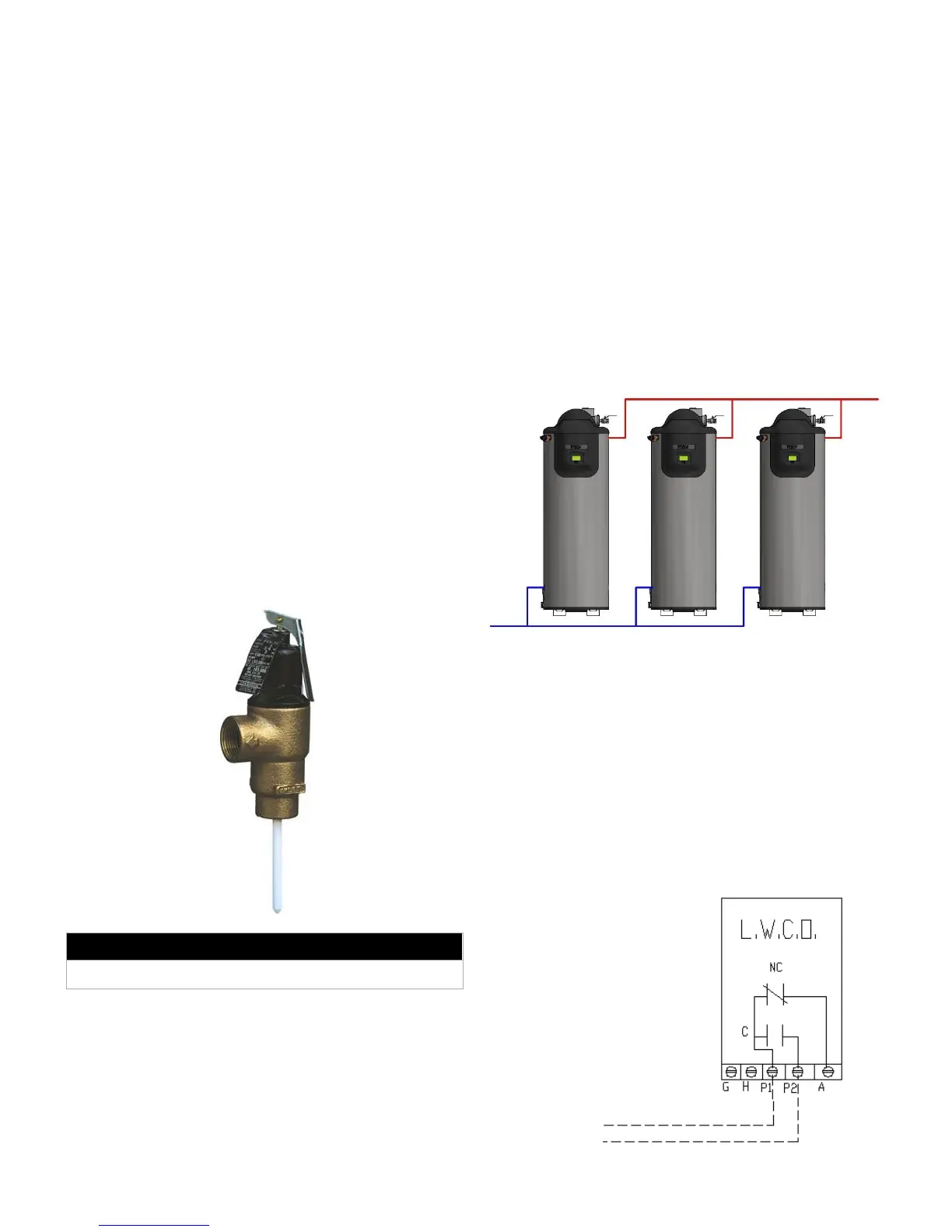
This appliance is supplied with a temperature and pressure
relief valve sized in accordance with ASME Water Heater and
Pressure Vessel Code, Section IV. The relief valve is installed
in the side of the pressure vessel near the top of the appliance.
To prevent water damage, the discharge from the relief valve
shall be piped to a suitable floor drain for disposal when relief
occurs. No reducing couplings or other restrictions shall be
installed in the discharge line. The discharge line shall allow
complete drainage of the valve and line. Relief valves should be
manually operated at least once a year. If a relief valve
discharges periodically, this may be due to thermal expansion in
a closed water supply system. Contact the water supplier or local
plumbing inspector on how to correct this situation. Do not plug
the relief valve.
T&P Relief Valve
NOTE: If the water heaters are used for charging a large storage
tank and installed with a pump circulating water between the tank
and this appliance, then an expansion tank connected to this loop
becomes the “Point of No Pressure Change”, since the pressure
at this point will remain constant regardless of pump operation.
In this case always pump away from the expansion tank
connection and into the VTech inlet connection. Pumping away
from the expansion tank means that the pressure on the suction
side of the pump is dissipated at the expansion tank, allowing the
pump differential to add pressure to the system, enhancing
system performance.
5.2 – Connecting to the Tank
All water connections are FNPT fittings. For ease of service,
install unions on the inlet and outlet of the appliance. The
incoming cold water must be connected to the lower port
connections on either the left or right side of the appliance. The
hot water supply to the building must be connected to the upper
port connections on either the left or right side of the appliance.
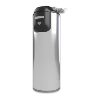
If multiple units are installed together, piping to the units must be
arranged such that each unit has the same length of pipe
connected to it, in order to balance the flow. The recommended
configuration would be “Reverse-Return”, where the unit closest
to the incoming supply connection is the furthest from the system
supply connection.
VTech Reverse-Return Piping Configuration
5.3 – Hydraulic Safeties
All safeties are installed in a common circuit, ensuring any safety
is capable of deactivating the unit. Please see the electrical
drawings in this manual for more information.
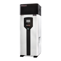
5.3.1 – Low Water Cut-off (LWCO)
If the VTech is installed above the hot water distribution system
(as is the case with penthouse mechanical room installations),
then a LWCO device may be required. Some local codes require
the installation of a LWCO on all systems. Low water cut-offs
should be tested every six months.
Watts LWCO - Electrical Connections