Section 01 TECHNICAL MANUAL
Subsection 01 (DYNAMIC POWER STEERING (DPS))
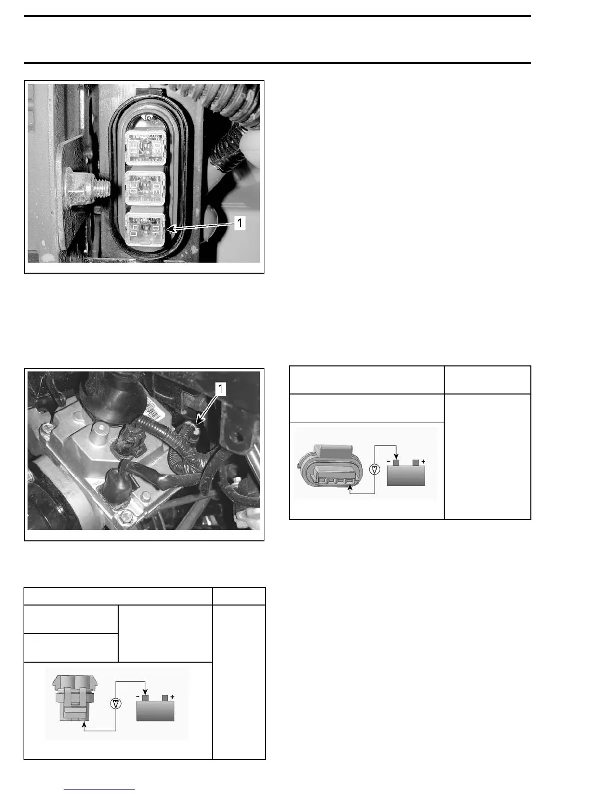
vmr2010-003-005_a
1. 40 amp DPS fuse (PF2-F3)
3. Replace fuse as required.
DPS Unit Input Voltage Test (Power
Side)
1. Disconnect the DPS PWR (power) connector.
vmr2010-003-013_d
1. DPS PWR connector (motor power)
2. Test for 12 Vdc DPS motor power at DPS2-A
and DPS2-B as per following table.
MULTIMETER PROBE POSITIONS VOLTAGE
DPS power
connector pin A
DPS power
connector pin B
Battery ground
Battery
voltage
rmr2008-028-091_a
If NO voltage is measured, test the 40 A DPS fuse
in the rear fuse box (PF2-F3). If good, check wires
and connector pins. Replace or repair defective
parts and reset fault codes.
If battery voltage is measured, carry out the fol-
lowing
DPS UNIT INPUT VOLTAGE TEST (CON-
TROL SIDE)
.
NOTE: This test may also be carried out by con-
necting a 12 Vdc test light between each DPS
PWR connector pins (A and B), and the battery (-)
negative terminal. The test light must come on
bright.
DPS Unit Input Voltage Test (Control
Side)
1. Disconnect DPS CTRL (control) connector and
turn ignition switch ON.
2. Set the ignition switch to ON.
3. Set the engine RUN/STOP switch to RUN.
4. Test for 12 Vdc power to the DPS module at
DPS1-A as per following table.
MULTIMETER PROBE
POSITIONS
VOLTAGE
DPS control connector (pin A)
and battery ground
Battery voltage
rmr2008-028-093_a
If NO voltage is measured, check wires and con-
nector pins from DPS unit to the Relays/Speedo
fuse in front fuse box (PF1-F4). Replace or repair
defective parts and reset fault codes.
If battery voltage is measured, carry out the fol-
lowing
DPS UNIT GROUND CIRCUIT TEST
.
NOTE: This test may also be carried out by con-
necting a 12 Vdc test light between the DPS con-
trol connector (pin A), and the battery (-) negative
terminal. The test light must come on bright.
DPS Unit Ground Circuit Test
1. Disconnect the DPS ground connector (GDN).
10 vmr2010-003