Section 01 TECHNICAL MANUAL
Subsection 02 (AIR CONTROLLED SUSPENSION (ACS))
vmr2010-004-108
Pressure Transducer Ground Test
1. Remove seats and RH side panel.
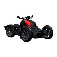
2. Disconnect pressure transducer connector.
vmr2010-004-104_a
1. Pressure transducer connector
3. Set the FLUKE 115 MULTIMETER (P/N 529 035
868)
to Vdc.
4. Place ignition switch to ON position.
5. Measure voltage as per the following table.
TEST PROBES VOLTAGE
Pin 1 (BK/GY)
Battery positive (+) post
Battery voltage
(± 12 Vdc)
Refer to the following illustration for the pressure
transducer connector pinout.
vmr2010-004-108
Pressure Transducer Replacement
1. Release air pressure, refer to
RELEASING AIR
PRESSURE IN SYSTEM FOR SERVICING
in this
subsection.
2. Disconnect pressure transducer connector.
3. Remove Oetiker clamp.
4. Remove pressure transducer from hose.
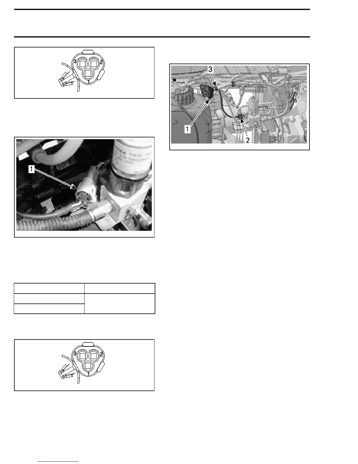
vmr2010-004-030_a
1. Auxiliary line pressure transducer
2. Connector
3. Oetiker clamp
5. Install a new pressure transducer on hose.
6. Install a new Oetiker clamp using
OETIKER PLI-
ERS (P/N 295 000 070)
.
7. Connect pressure transducer connector.
8. Ensure that there is no air leaks from pressure
transducer hose. Refer to
ACS SYSTEM LEAK
TEST (WITH B.U.D.S.)
.
ACS HOSES
ACS Hose and Fitting Replacement
1. Release air pressure, refer to
RELEASING AIR
PRESSURE IN SYSTEM FOR SERVICING
in this
subsection.
2. Locate hose or fitting to be replaced.
3. Remove it from vehicle.
4. Install the new hose or fitting.
5. Perform a
ACS SYSTEM LEAK TEST (WITH
B.U.D.S.)
.
Auxiliary Line Adapter Replacement
1. Release air pressure, refer to
RELEASING AIR
PRESSURE IN SYSTEM FOR SERVICING
in this
subsection.
2. Disconnect auxiliary line hose from adapter as
follows:
2.1 Push fitting ring toward adapter.
2.2 Hold ring in place.
2.3 Pull air hose.
44 vmr2010-004