Section01 TECHNICAL MANUAL
Subsection 02 (AIR CONTROLLED SUSPENSION (ACS))
vmr2010-004-001_a
1. Pneumatic valve cap
4. Push and hold pneumatic valve pin using a small
screwdriver.
vmr2010-004-002
5. Wait until the system is completely empty of
air.
NOTE: Make sure to wait enough time in order to
let the system expel the air. (no more pressurized
air sound from the valve).
6. Reinstall pneumatic valve cap.
SYSTEM DESCRIPTION
(COMPONENTS)
Fuse and Relay
ACS Fuse (F14)
1. ACS fuse (F14) is located in the front fuse box.
FRONT FUSES BOX
NO DESCRIPTION RATING
F14 ACS 20 A
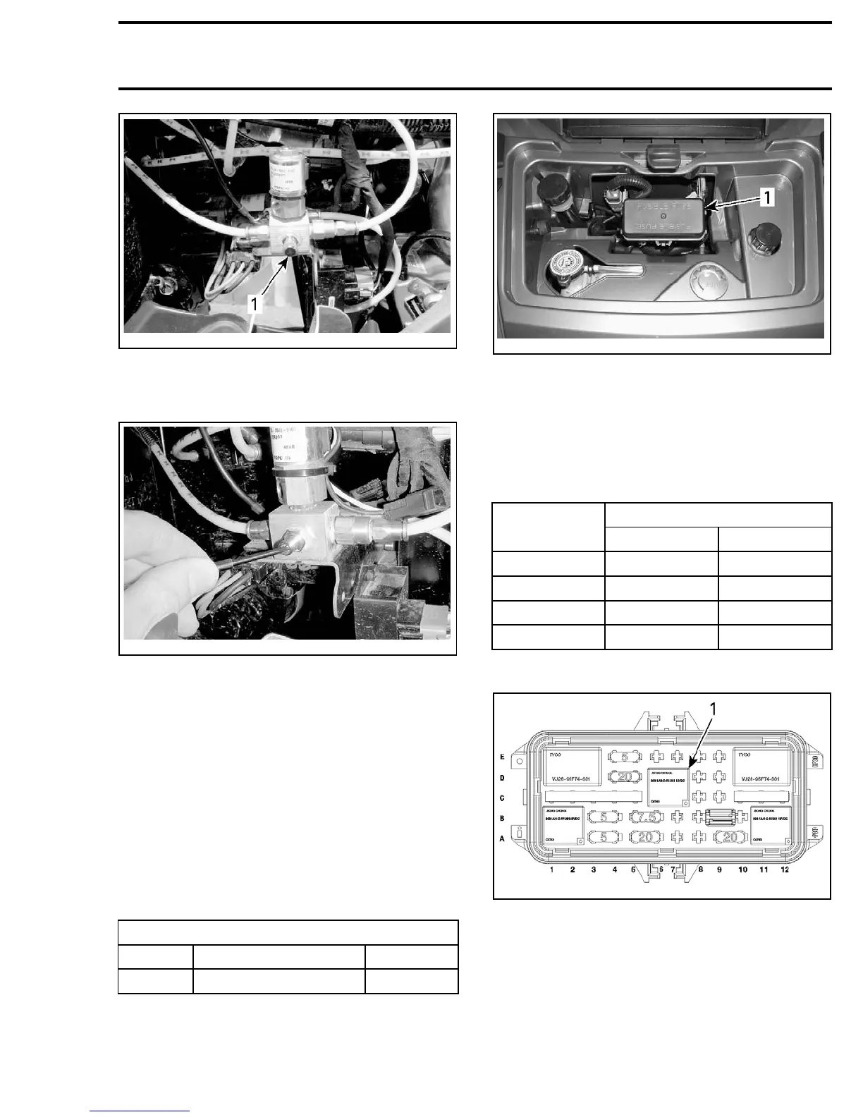
vmo2007-003-017_b
TYPICAL - FRONT SERVICE COMPARTMENT
1. Front fuse box
ACS Compressor Relay (R5)
Compressor relay is located in the front fuse box,
under front service compartment panel. Note that
therelayisnotatthesamepositionona500LTD
andona800RLTDmodels. Refertothefollowing
table.
FRONT FUSE BOX PIN
RELAY (R5)
TERMINAL
500 LTD 800R LTD
86 6D 11B
85
7C
12A
30 7D 12B
87
6C
11A
Outlander 500 LTD
vmr2010-004-107_a
OUTLANDER 500 LTD MODEL
1. ACS compressor relay (R5)
vmr2010-004 27