Section 01 TECHNICAL MANUAL
Subsection 01 (DYNAMIC POWER STEERING (DPS))
20. Install and connect ECM. Torque ECM mount-
ing screws to 7 N•m (62 lbf•in).
21. Install dash board and reconnect the following:
– Multifunction gauge
– Ignition switch
– 12 Vdc accessories outlet.
22. If installing a replacement DPS unit, refer to
DPS REPLACEMENT
in this subsection.
23. Perform the torque offset reset. Refer to
TORQUE OFFSET RESET
in this subsection.
24. Install all other removed parts in the reverse
order of removal.
25. Carry out a test ride of the ATV to ensure
proper operation of the DPS unit.
DPS Unit Replacement
New DPS units do not come with the required
software programmed into the unit. A DPS unit
fault will be generated when the vehicle is pow-
ered up. The check engine light will come on and
a DPS FAULT message will appear in the multi-
function gauge.
When DPS unit installation is complete, carry out
the following steps.
1. Connect the ATV to the latest B.U.D.S. soft-
ware.
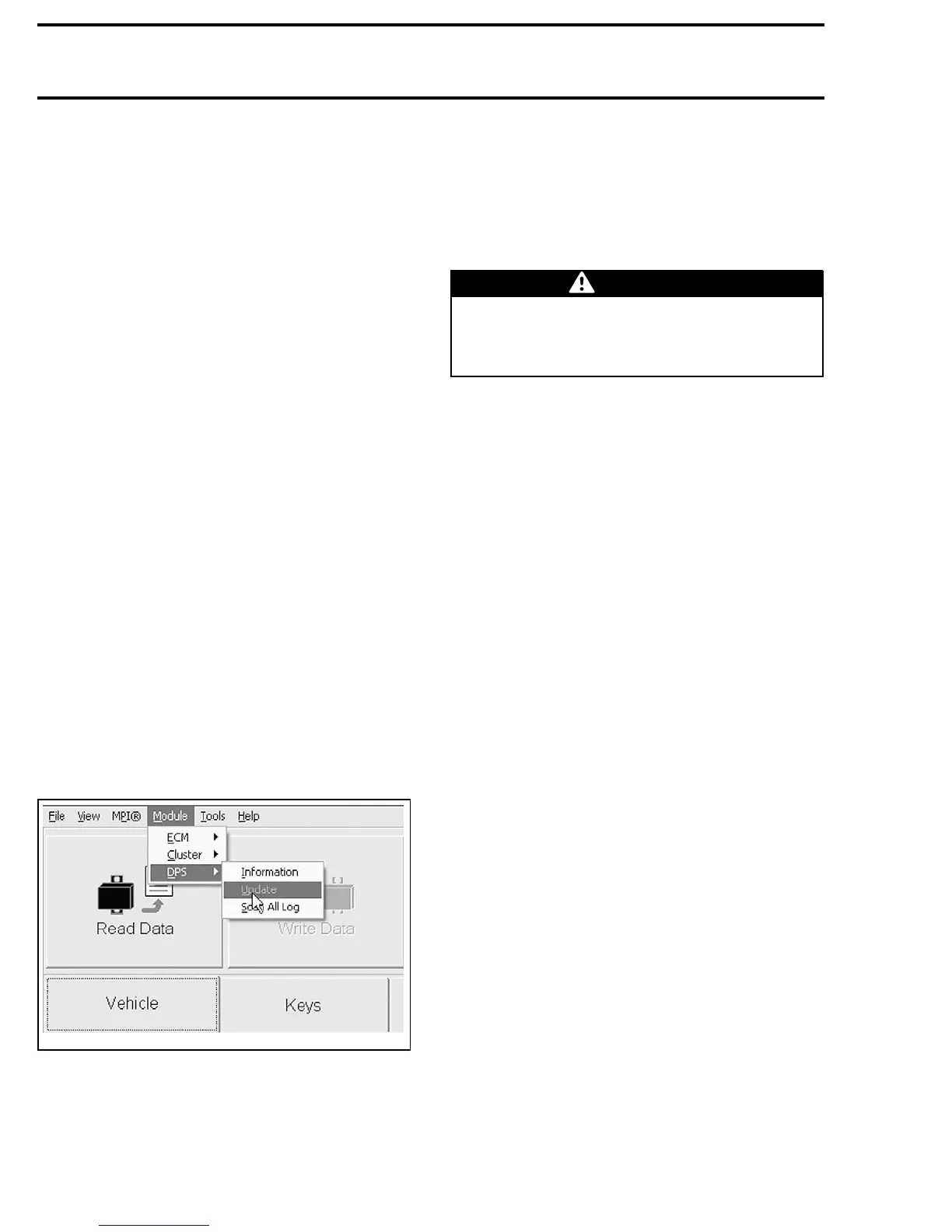
2. Select the Read Data button.
3. In the Module menu, choose the DPS sub-
menu and install the latest DPS software
Update file as applicable to the type ATV (Out-
lander or Renegade).
vmr2010-003-040
DPS SOFTWARE UPDATE
4. Once the correct DPS soft
ware file is installed,
go to the Faults page an
d clear the fault codes.
5. Carry out the
TORQUE OFFSET RESET
proce-
dure as described in this subsection.
6. Test drive the ATV to ensure proper DPS oper-
ation.
PITMAN ARM
If the pitman arm requires replacement, the DPS
unit MUST be replaced.
WARNING
DO NOT attempt to replace or repair the pit-
man arm. Do not use a torch or arc welder on
the pitman arm. Failure to comply will result
in DPS unit malfunction.
22 vmr2010-003