Section01 TECHNICAL MANUAL
Subsection 02 (AIR CONTROLLED SUSPENSION (ACS))
3. Rinse the prefilter with warm water until all
cleaning solution disappears.
4. Let the prefilter dry completely.
Filter (Disc) Cleaning
1. Blow low pressure compressed air on filter to
clean it.
NOTICE
Do not wash the filter (disc) with any
cleaning solution.
Housing Cleaning
1. Blow low pressure compressed air in housing
to clean it.
PRESSURE TRANSDUCER (ACS
AUXILIARY LINE)
Pressure Transducer Signal Circuit
Continuity Test
1. Remove seats and RH side panel.
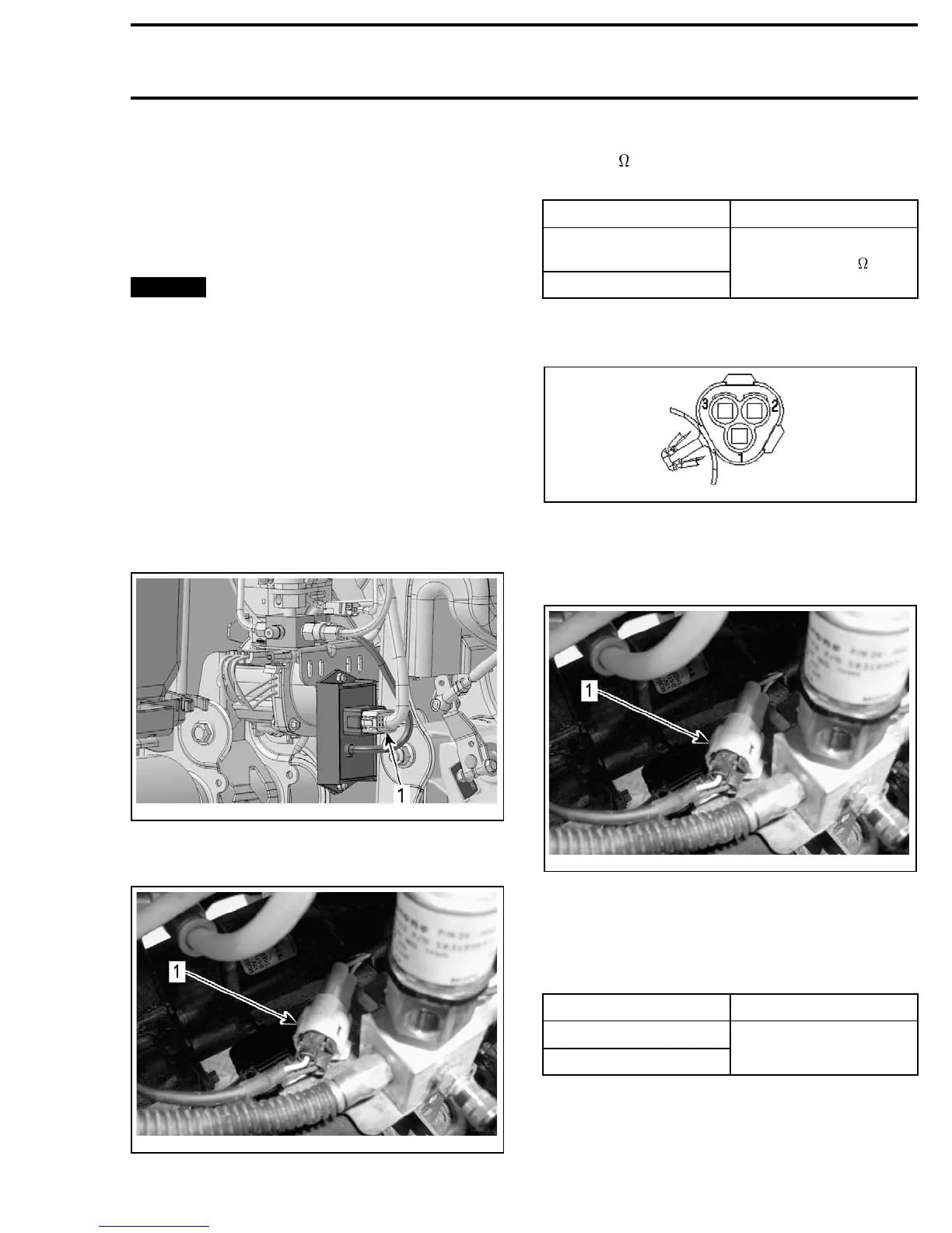
2. Disconnect module connector.
vmr2010-004-011_a
1. Module connector
3. Disconnect pressure transducer connector.
vmr2010-004-104_a
1. Pressure transducer connector
4. Set the FLUKE 115 MULTIMETER (P/N 529 035
868)
to .
5. Measure resistance as per the following table.
TEST PROBES RESISTANCE
Pressure transducer
pin 2 (PK/BR)
Module pin 3 (PK/BR)
Close to 0
Refer to the following illustration for the pressure
transducer connector pinout.
vmr2010-004-108
Pressure Transducer Input Voltage Test
1. Remove seats and RH side panel.
2. Disconnect pressure transducer connector.
vmr2010-004-104_a
1. Pressure transducer connector
3. Set the FLUKE 115 MULTIMETER (P/N 529 035
868)
to Vdc.
4. Place ignition switch to ON position.
5. Measure voltage as per the following table.
TEST PROBES VOLTAGE
Pin 3 (PK/OR)
Battery negative (-) post
Battery voltage
(± 12 Vdc)
Refer to the following illustration for the pressure
transducer connector pinout.
vmr2010-004 43