Section01 TECHNICAL MANUAL
Subsection 02 (AIR CONTROLLED SUSPENSION (ACS))
ACS MODULE
ACS Module Signal Circuit Continuity
Test
1. Remove seats and RH side panel.
2. Disconnect multifunction gauge from vehicle.
Refer to
LIGHTS, GAUGE AND ACCESSORIES
subsection of the appropriate Shop Manual.
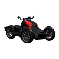
3. Disconnect ACS module connector.
vmr2010-004-011_a
1. Module connector
4. Set the FLUKE 115 MULTIMETER (P/N 529 035
868)
to .
5. Measure resistance as per the following tables.
TEST PROBES RESISTANCE
Gauge pin 18 (BK/BE)
Modulepin5(BE/GN)
Closeto0
TEST PROBES RESISTANCE
Gauge pin 19 (BE/GN)
Module pin 6 (WH/BE)
Closeto0
ACS Module Input Voltage Test
1. Remove seats and RH side panel.
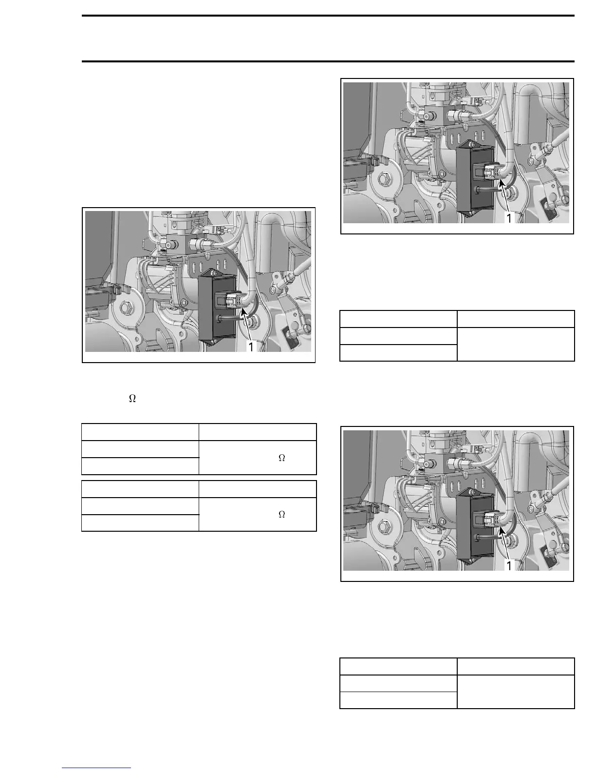
2. Disconnect module connector.
vmr2010-004-011_a
1. Module connector
3. Set the FLUKE 115 MULTIMETER (P/N 529 035
868)
to Vdc.
4. Place ignition switch to ON position.
5. Measure voltage as per the following table.
TEST PROBES VOLTAGE
Pin12(OR/GN)
Battery negative (-) post
Battery voltage
(± 12 Vdc)
ACS Module Ground Test
1. Remove seats and RH side panel.
2. Disconnect module connector.
vmr2010-004-011_a
1. Module connector
3. Set the FLUKE 115 MULTIMETER (P/N 529 035
868)
to Vdc.
4. Place ignition switch to ON position.
5. Measure voltage as per the following table.
TEST PROBES VOLTAGE
Pin 7 (BK)
Battery positive (+) post
Battery voltage
(± 12 Vdc)
vmr2010-004 35