UNCRATING
rbs2010-012-010_a
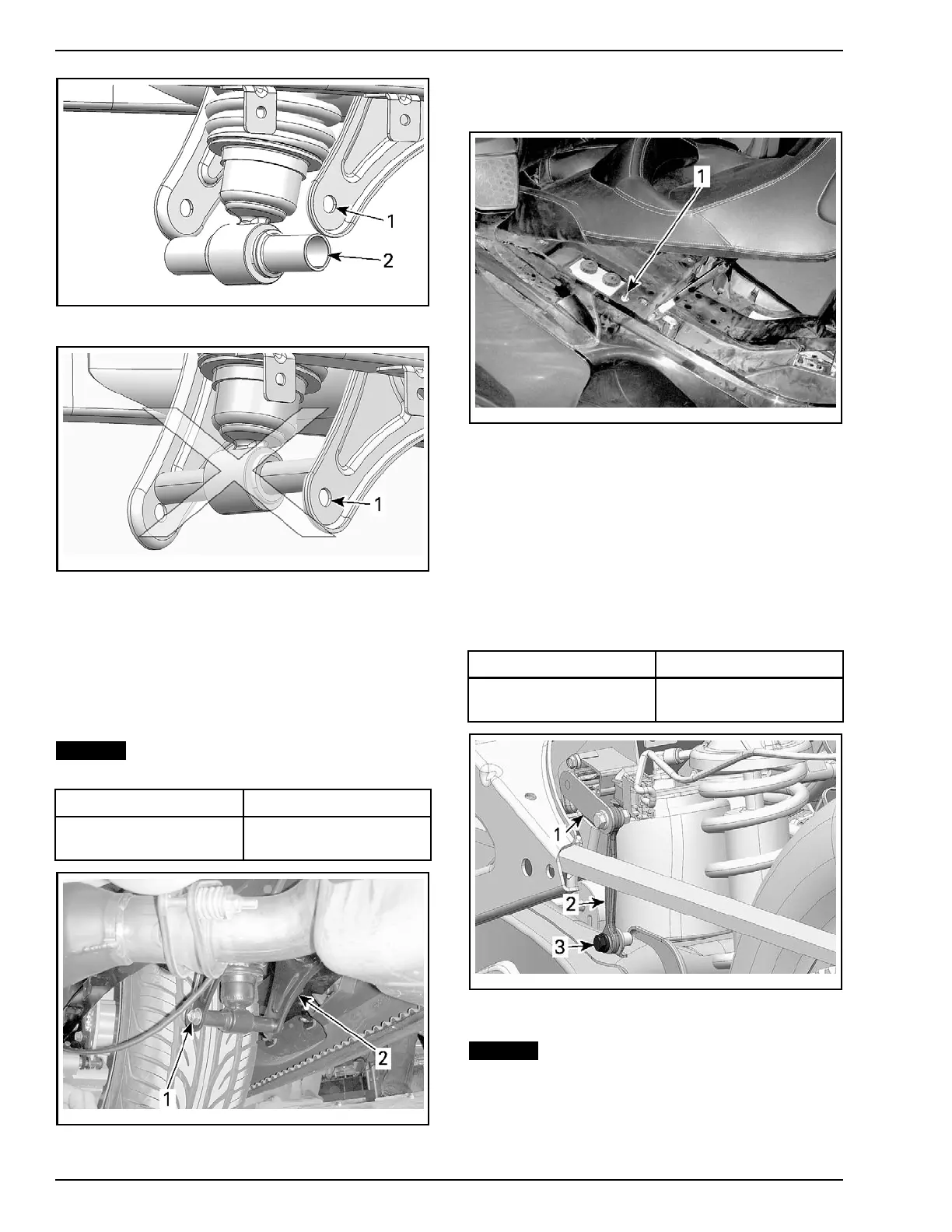
1. Lower shock bracket hole
2. Lower shock anchor pin
rbs2010-012-004_a
1. Lower bracket hole
7. Secure shock absorber as follows:
7.1 Using the p assenger grab handles, slightly
lift the rear of the vehicle by HAND to align
both bushings on lower bracket hole.
7.2 Install M10 x 140 hexagonal flange screw.
7.3 Install M10 elastic flange nut.
NOTICE
Apply specified torque to the hexag-
onal flanged screw, not the nut.
PA RT SPECIFIED TORQUE
M10 he
xagonal flanged
screw
48 N•m (35 lbf•ft)
rbl
2010-002-022_a
1. Shock absorber screw
2. Lower bracket
8. Install cap on ACS suspension manual inflation
valve.
rmo2010-001-056_a
1. Captoinst
all
RT-S and RT Limited Models
9. Install th
e link of the ACS position sensor on the
swing arm.
9.1 Position the ACS position sensor lever
rearward.
9.2 Place the link on the outside of swing arm
bracket.
9.3 Secure th
e link using M6 x 20 hexagonal
flange s
crew (from PDI kit)
PART SPECIFIED TORQ UE
M6 x 2 0 hexagonal
flange screw
4N•m (35lbf•in)
rbl2011-001-001_a
1. ACS position sensor lever
2. ACS position sensor link
3. M6 x 20 hexagonal flange screw
NOTICE
Ensure that ACS position sensor
lever o rientation is correct.
12 / 52 2014-1 PREDELIVERY

 Loading...