4. MECHANICAL SYSTEM
4-112
COPYRIGHT
©
2001 CANON INC. CANON CLC1000/1000S/3100 REV.2 MAY 2001 PRINTED IN JAPAN (IMPRIME AU JAPON)
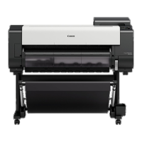
4) Disconnect the three connectors [2], and
remove the two screws [3]; then, remove the
analog processor [4].
Figure 4-1105-11
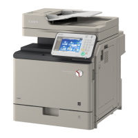
12. Removing the Image Processor
PCB and the Memory PCB
1) Remove the two fixing screws [1], and fix the
digital unit [2] in place as indicated.
Figure 4-1101-12 (fixing screw position)
Figure 4-1102-12 (fixing position)
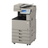
2) Remove the two screws [3], and remove the
front cover [4] of the digital set.
Figure 4-1103-12
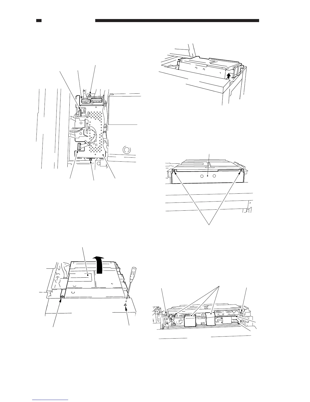
3) Disconnect the three connectors [5] each, and
remove the two screws [6] each; then, slide
out the image processor PCB [7] and the
memory PCB [8].
Figure 4-1104-12
[2]
[2]
[3]
[4]
[2]
[3]
[2]
[1]
[1]
[3]
[4]
[6]
[6]
[5]
[7]
[8]