COPYRIGHT
©
2001 CANON INC. CLC1000/1000S/3100 REV.2 MAY 2001 PRINTED IN JAPAN (IMPRIME AU JAPON)
4-113
4. MECHANICAL SYSTEM
13. Removing the Video Controller
PCB
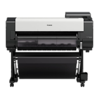
1) Fix the digital unit [1] as indicated in Figure 4-
1101-13 (See chapter 4. VI. LASER SYSTEM,
A-1. Making Preparations for Laser Unit-
Related Parts).
Figure 4-1101-13
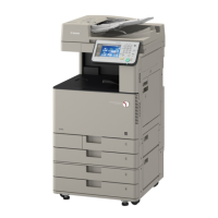
2) Remove the three screws [2], and remove the
air duct plate [3].
Figure 4-1102-13
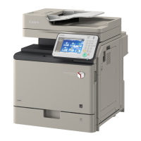
3) Disconnect all eleven connectors from the
video controller PCB, and remove the four
mounting screws [4]; then, remove the video
controller PCB [5].
Figure 4-1103-13
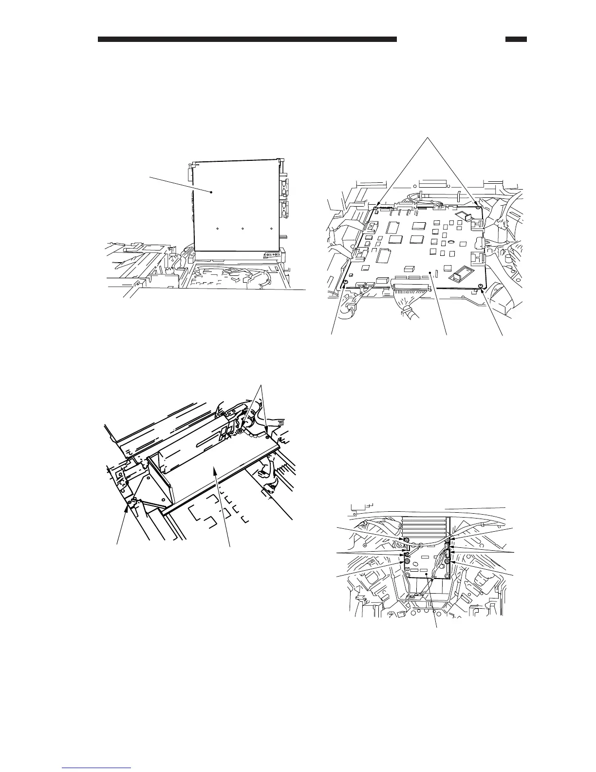
14. Removing the Polygon Motor
Driver
1) Make preparations for parts associated with
the laser unit.
2) Disconnect the four connectors [1], and
remove the four screws [2]; then, remove the
polygon motor driver [3].
Figure 4-1101-14
[1]
[2]
[2]
[3]
 Loading...