Chapter 2
2-1
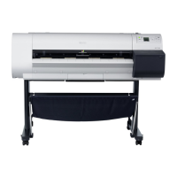
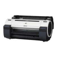
2.1 Basic Operation Outline
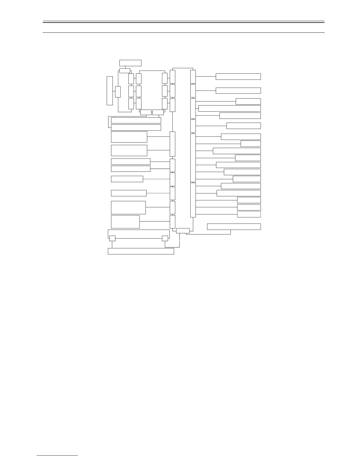
2.1.1 Printer Diagram
0012-6242
A printer diagram is shown below.
F-2-1
2.1.2 Print Driving
0013-5398
At printing, print signals and control signals are output to the printhead via the carriage relay PCB and Head relay PCB to discharge inks from the nozzle assembly.
The printhead six trains of nozzles arranged in a zigzag pattern.
This printer uses only one printhead.
(Installed from left to right: C, M, Y, MBk, MBk and Bk)
Two kinds of print signals are transferred to each nozzle train according to the data transfer clock and the data pulse timing: even-numbered nozzle data and odd-
numbered nozzle data.
Drive control signals fall into two types: heat enable signals and subheat enable signal. The heat enable signal allows inks to be discharged from the nozzles, whereas
the subheat enable signal heats the head to an optimal temperature to keep the rate of ink discharge constant.
J3401
J3201J3202J3002J2501 J2502
J3602J3601J2702J3001J1301J2801J2601
Main controler PCB
Linear encoder
Carriage cover sensor
Upper cover lock
solenoid(R)
Upper cover lock
solenoid(L)
Upper cover switch
Upper cover switch
Valve motor
Ink tank cover switch
Carriage motor
Head management sensor
Feed roller motor
Printhead
Multi sensor
J101J102J103
J601J702J703
J201J202
J101
J201
J601
J102J103
Head relay PCB
Carriage
relay PCB
Ink tank ROM PCB (L)
Ink tank ROM PCB (R)
Humidity sensor
Carriage HP sensor
Lift motor
Pressure release switch
Pump motor
Pump encoder sensor
Pump cam sensor
Media sensor
J2701
Feed roller encoder
Feed roller HP sensor
Suction fan
Mist fan (R)
Mist fan (L)
Maintenance cartridge
J1801
J3301
Power supply
Operation panel
J2 J1
Maintenance cartridge ROM PCB
Valve open/closed detection Sensor
 Loading...