Chapter 2
2-12
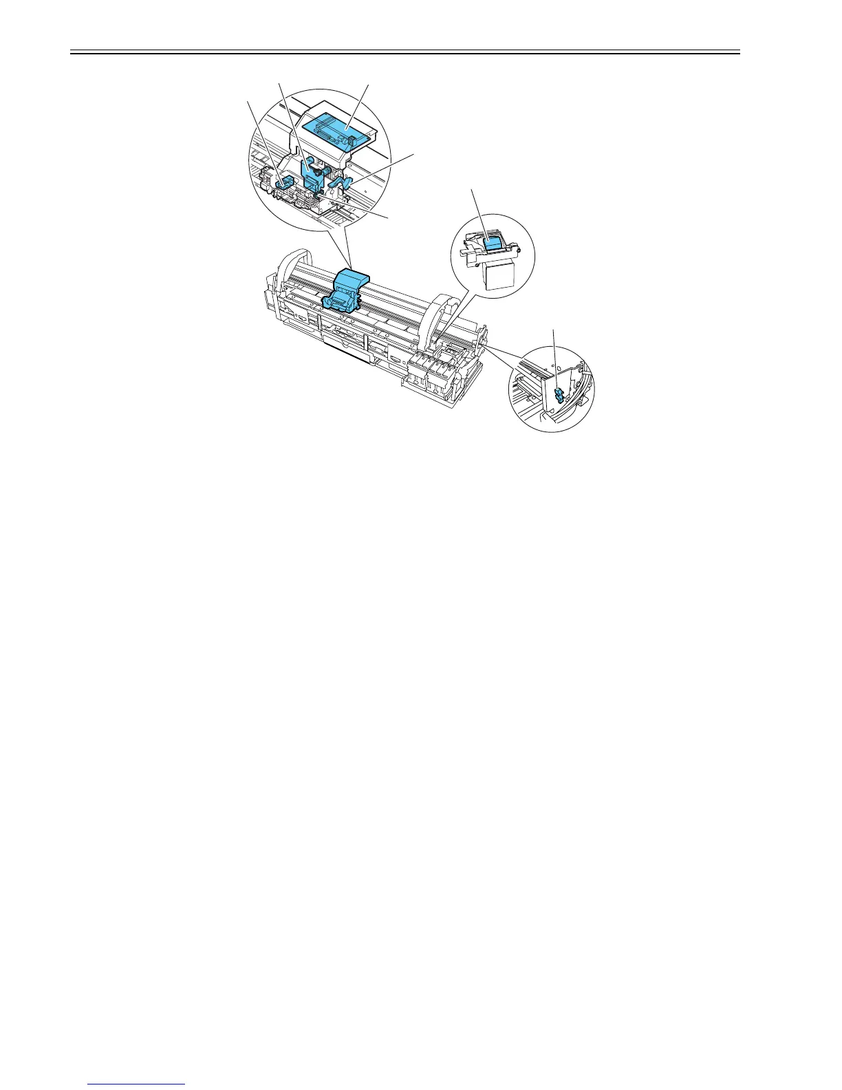
F-2-9
e) Printhead maintenance unit
This printer cleans the printhead with the carriage halted at its home position.
Wiping is executed in sync with the rotation of the motor. Wipers mounted on the carriage wipe the printhead while the carriage is halted at its home position.
A maintenance jet is discharged as the carriage travels to pass the maintenance jet tray to the right of the plant.
A suction operation is carried out by a suction cap in t he purge unit.
f) Carriage height adjustment unit
When the lift motor is driven to rotate the lift lever, the carriage shaft height is varied to change the separation between the face of the printhead and the paper.
The printhead height is detected by the multisensor attached to the lower left part of the carriage
g) Multisensor
The multisensor attached to the lower left part of the carriage consists of four LEDs (red, blue, green, infrared) and two light-receiving sensors to detect the leading
edges and width of paper and skews in it, and to adjust its registration and head height.
The multisensor standard has a white plate attached to it, so that a reference value can be calculated during paper gap measurement by measuring the intensity of
light reflected upon the white plate.
(Service mode: SERVICE MODE > ADJUST > GAP CALIB)
h) Rail cleaners
The shaft cleaners located on both sides of the carriage clean the carriage shaft and give a coat of an imprenating oil to the shaft.
i) Internal unit temperature sensor
One thermistor is installed on the head relay PCB on the back of the head holder to detect the internal unit temperature.
Carriage relay PCB
Head relay PCB
Carriage cover
sensor
multi sensor
Sensor Flag
lift cam sensor
Maintenance-jet tray
 Loading...