3-10
Part 3: Adjustment
[For LV-S2U / LV-S2E]
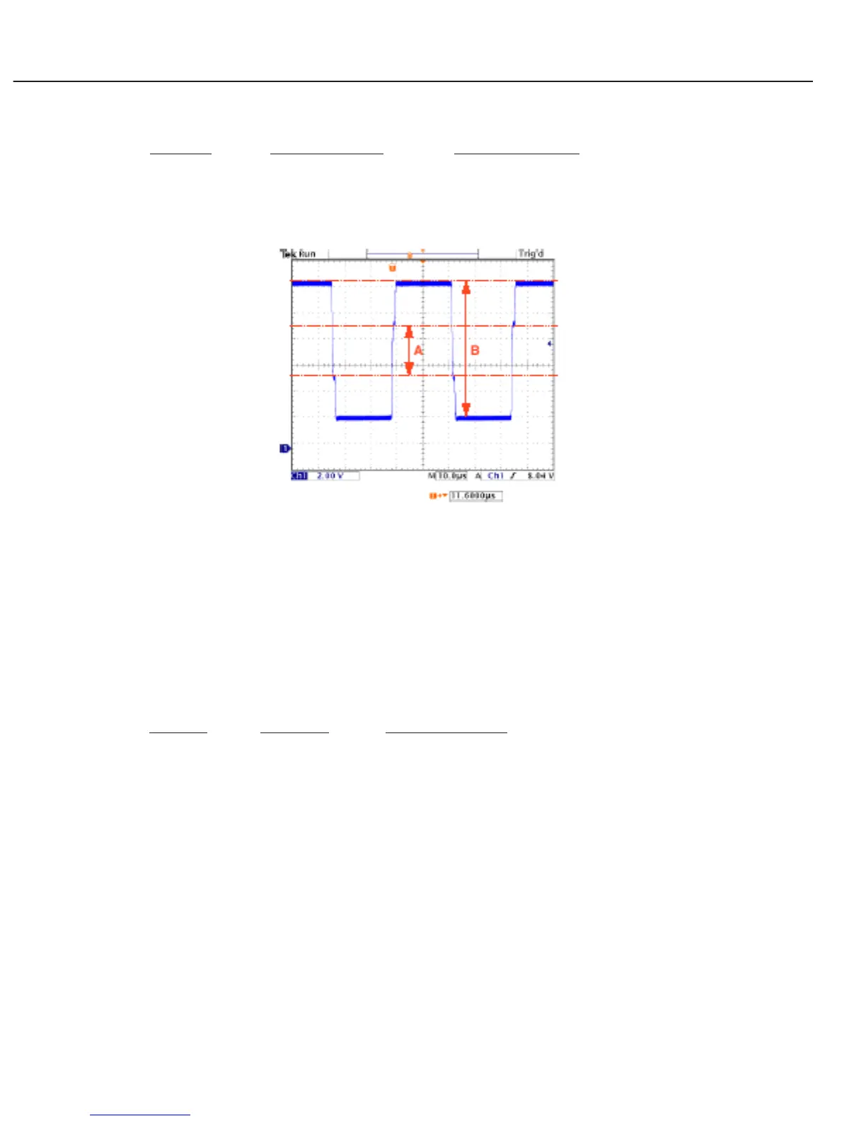
Item no. Adjustment part Adjustment value
22 DC level-A in a figure 3.8V ± 0.1 V-DC.0
23 DC level-B in a figure 10.0V ± 0.5 V-DC.
Fig. 3-3
2.3 Signal Center DC Voltage Adjustment
Measuring equipment ............Digital voltmeter
Input mode ............................Computer
Input signal ...........................16-step gray scale
Enter the service mode.
Adjust the voltage at each test point to the following value with the VOLUME +/- button.
Item No. Test point Adjustment value
1 TP-R1 7.5V ± 0.05V DC
2 TP-G1 7.5V ± 0.05V DC
3 TP-B1 7.5V ± 0.05V DC
 Loading...