MAP1 Page 11 of 31
Installation Manual June 2018 • Rev. 1.6
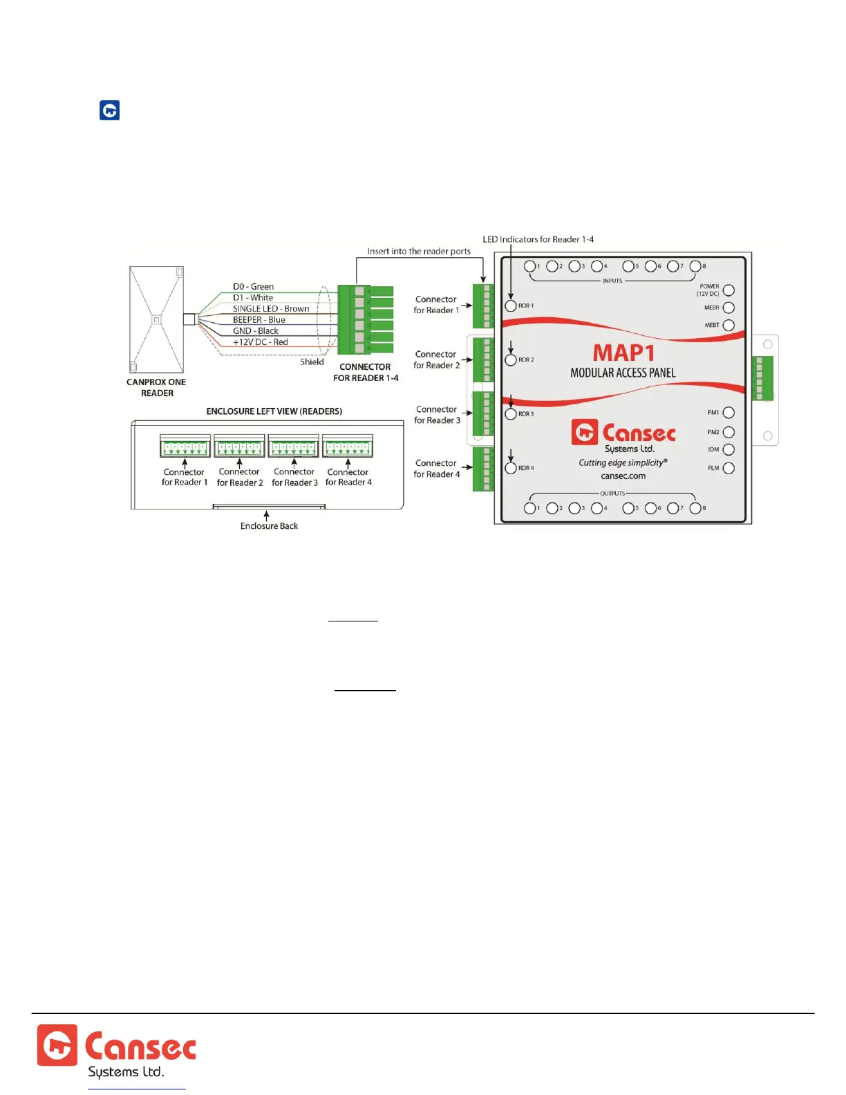
ENTRY READER WIRING
The following diagram shows entry reader wiring only. For entry and optional exit
reader wiring diagram, proceed to the next section.
READER LED ON = Reader Active. Two Inputs and two Outputs are used for
RTE/REX, door contacts well as lock relays and multi-function relays respectively.
READER LED OFF = Reader Inactive. Two Inputs and two Outputs are free to be
used as independent auxilliary Input and Output points.