MAP1 Page 10 of 31
Installation Manual June 2018 • Rev. 1.6
Panel Installation
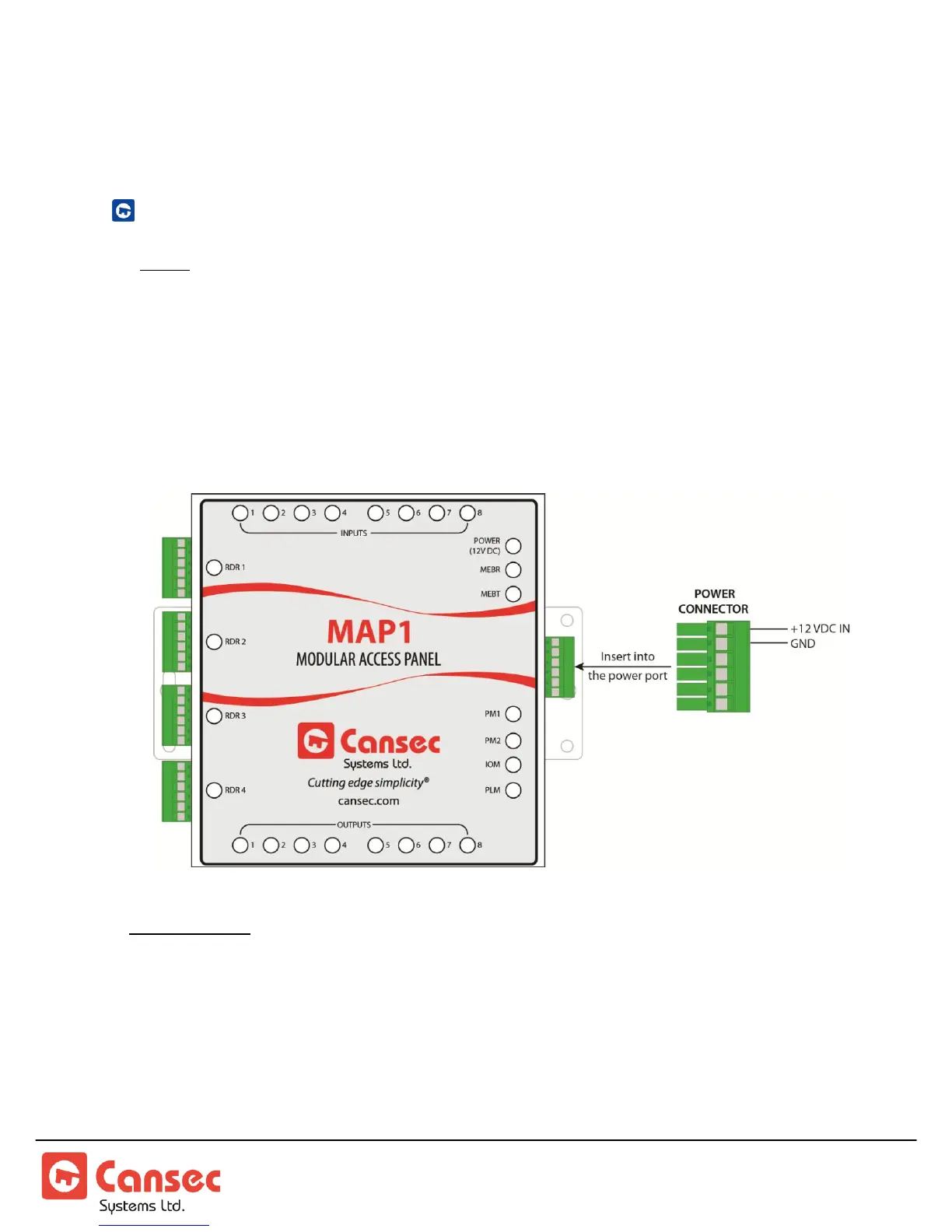
CONTROLLER POWER CONNECTION
Note: See Note 1 in Appendix section for suggested power supplies & backup battery.
The MAP1 requires an external battery backed-up 12 VDC power supply. However,
as many devices can be attached to the MAP1 controller, it may be more cost
effective to use a separate power supply (battery backed-up) just for the MAP1
Controller and a separate power supply which can be sized to supply the amount of
current that the attached high-current devices (locks) will require.
Mode Indicator: After a complete power up, PM1 LED is on, PM2 LED is off, IOM LED flashes
once every second, PLM LED flashes waiting for a host connection and stays
steady when a connection is established. MAP1 emits beep to indicate
operating mode.
1 Beep – First Access
2 Beeps – Webster
3 Beeps – Cloud Lock