MAP1 Page 12 of 31
Installation Manual June 2018 • Rev. 1.6
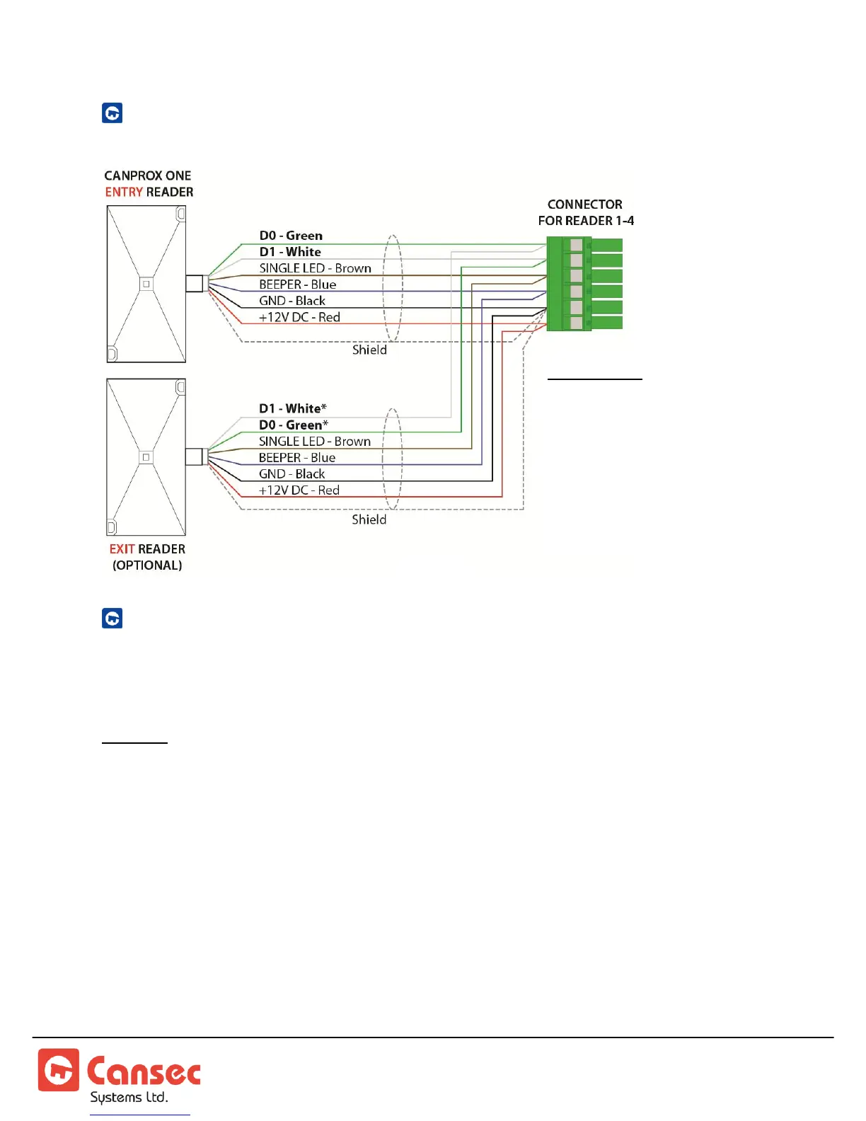
ENTRY AND EXIT READER WIRING
EXIT BUTTON AND DOOR CONTACT WIRING
The MAP1 controller can be provisioned for up to 4 doors. The following shows the
input usage for each door combination.
Caution: When moving the MSJx - MicroShunt jumpers (small and easily dropped, accuracy is
important during movement) it is advisable to set up the MAP1 Controller prior to attaching it
to a surface. It is highly recommended that the MAP1 be removed from the attached surface to
do a change of the MSJx position. See figure 6 below.
Reader 1: uses Input 1 (Door Contact/DPS) and Input 2 (RTE/REX).
Reader 2: uses Input 3 (Door Contact/DPS) and Input 4 (RTE/REX).
Reader 3: uses Input 5 (Door Contact/DPS) and Input 6 (RTE/REX).
Reader 4: uses Input 7 (Door Contact/DPS) and Input 8 (RTE/REX).
Note: Both door contact and exit button inputs have voltage present on the circuits. Only
connect dry contact devices to these inputs.
Exit Reader:
*D1 (White) of exit reader
connects to D0 (Green) of
entry reader.
*D0 (Green) of exit reader
connects to D1 (White) of
entry reader.