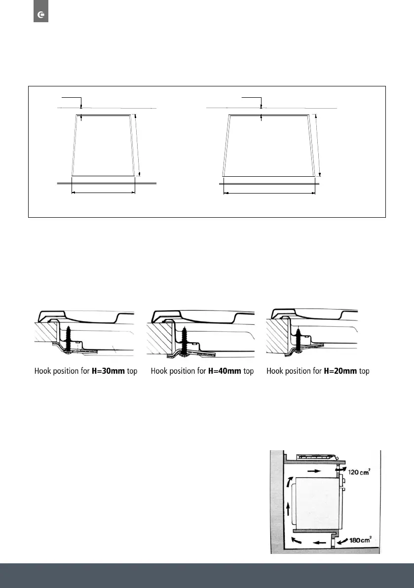
provided which allow installation of the hob in worktops that measure 20 to 40mm in
thickness (see Fig. 6). It is advisable to use all the fixing supplied.
wood panel must be inserted as insulation. This panel must be
When installing on a built-in oven without forced ventilation, ensure that there are air inlets and outlets for
ventilating the interior of the cabinet adequately.
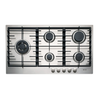
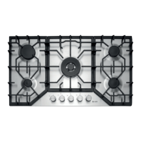
Gas connection for gas hob
The hob should be connected to the gas-supply by a Gas safe registered installer. During installation of this
product it is essential to fit an approved gas tap to isolate the appliance from the supply for the convenience
of any subsequent removal or servicing. Connection of the appliance to the gas mains or liquid gas must be
carried out in compliance with current regulations, and only after it is ascertained that it is adaptable to the
type of gas to be used. If not, follow the instructions indicated in the paragraph headed "Adaptation to
different gas types". In the case of connection to liquid gas, by bottle/tank, use pressure regulators that
conform to current regulations in force.
Important: For safety, for the correct regulation of gas use and long life of the appliance, ensure that the
gas pressure conforms to the indications given in table 1 "Burners and injector specifications".
Connection to Gas supply by rigid metal pipe
(Copper or steel)
Connection to the gas source must be done in such a way as to not create any stress points at any part of
the appliance.
The appliance is fitted with a 1/2” gas male ‘L’ shaped union and a gasket for the attachment to the gas
supply.
Should this union have to be re-positioned, the gasket must be replaced.
Connection to flexible steel tube
The gas feed connector to the appliance is a threaded, male 1/2" connector for round gas pipe. Only use
pipes and sealing gaskets that conforms to the standards currently in force. The maximum length of the
flexible pipes must not exceed 2000 mm. Once the connection has been made, ensure that the flexible
metal tube does not touch any moving parts and is not crushed.
Check the Installation
Once the appliance has been installed, make sure all the connections are properly sealed, using liquid
detector fluid and a ‘U’ gauge. Never use a flame.
Electrical Connection
(The hob is fitted with a standard 13amp plug)
Fit the supply cable with a standard plug for the demand rate indicated on the rating plate or connect it
directly to the electrical mains. In the latter case, a single pole switch must be placed between the appliance
and the mains, with a minimum opening between the contacts of 3 mm in compliance with current safety
codes (the earth wire must not be interrupted by the switch). The power supply cable must be positioned so
that it does not reach a temperature in excess of 50~C above room temperature at any point.
Before actual connection make sure that:
Fig.5 Fig.6
d) Should the hob be installed directly under a cupboard, the cupboard should be at least 700mm from the
worktop, as shown in Fig.5.
e) The cut out dimensions for the worktop must be those indicated in the figures shown below. Fixing hooks
are provided which allow place the hob plate on work tops that measure 20 to 40 mm in thickness (see
Fig. 6).To obtain a of the hob plate it is advisable to use all the fixing supplied.
Fig.6