Instruction manual INCH
Please keep this instruction manual for future reference
11
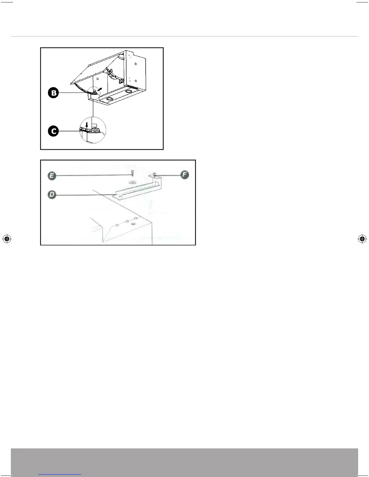
To secure the product to the wall you must initially remove the grease filters. This is achieved by
opening the front panel and pushing the two catches (A) upwards which will then release the grease
filters. Once the grease filters have been removed the front door panel should also removed.
Open
the
front panel and remove the two screws (B) as illustrated above. Press the tab (C) down
and remove the front panel from its guides
Secure brackets (D) onto the top of the extractor using the fitting screws and washer (E)
provided. Check that adjustment screw (F) is fitted.
Note: Note some units this bracket may already be fitted.
2
Open the front panel and remove the
two screws (B) as illustrated above. Press
the tab (C) down and remove the front
panel from its guides
Secure brackets (D) onto the top
of the extractor using the fitting
screws and washer (E) provided.
Check that adjustment screw (F) is
fitted.
Note: Note some units this bracket
may already be fitted.
Ensuring there is a minimum distance if 65cm between the bottom of the extractor
and hob surface., the two mounting brackets (G) to the rear wall.
Once the two mounting brackets are in position hook the extractor mounting
bracket (D) onto the wall mounting bracket
Some adjustment is provide within the brackets. For forward and backward
adjustment use screw (E) and for height alignment adjust screws (F).
Once the adjustment is complete fully tightening all screws.
If after installation there is a gap between the rear wall and the extractor a spacer is
provided. This can be fixed to the rear of the extractor and cut to accommodate the
gap.
INCH Instruction manual.indd 11 06/07/2017 14:45