32
Sequence of Operation
To better understand the heater, it is easier to break the unit out into smaller individual systems. There are
two main systems, a make-up air fan, and a heater. The make-up air fan consists of a blower and motor.
The heater may be further broken down into two control systems, the Flame Safety Control (FSC) and the
Modulating Gas System (MGS). The burner mixes air with the gas (Natural or LP), which heats the air.
Flame Safety Control
The first system to understand is the Flame Safety Controller. The FSC is there only to monitor the flame,
NOT to control the temperature. The FSC uses a flame rectification sensor mounted on the pilot assembly
to detect the presence of flame in the burner.
The FSC also works with the airflow sensor, which relays if there is proper airflow through the unit (not just
any airflow, but proper
airflow). Proper airflow occurs when there is a .15” w.c. to .80” w.c. differential
pressure drop across the burner. The FSC controls the opening of the redundant solenoid gas valves
and the operation of the spark igniter to initiate a pilot flame upon start-up.
Upon a call for heat, there is a 15 second Pilot Trial For Ignition (PTFI). During PTFI, the FSC opens the
pilot gas valve and allows gas to flow to the pilot assembly. At the same moment, the spark igniter is
started, causing the spark to ignite the pilot gas. When the flame rod sensor detects the flame it powers the
modulating gas system. This is the normal operating mode. The FSC continues to monitor the flame and
airflow. Once this occurs, the unit is in a main flame cycle and thus powers the main gas valve and the
modulating gas system. This is the normal operating mode. The FSC continues to monitor the flame and
airflow. If the flame fails to light after 15 seconds of sparking, the FSC goes in to lock-out mode. Anytime
this occurs, the problem must be diagnosed and corrected to avoid future lockouts after resetting. To begin
troubleshooting, or to reset the FSC, shut down power to the heater and restart the heater. This will clear
the alarm from the flame safety.
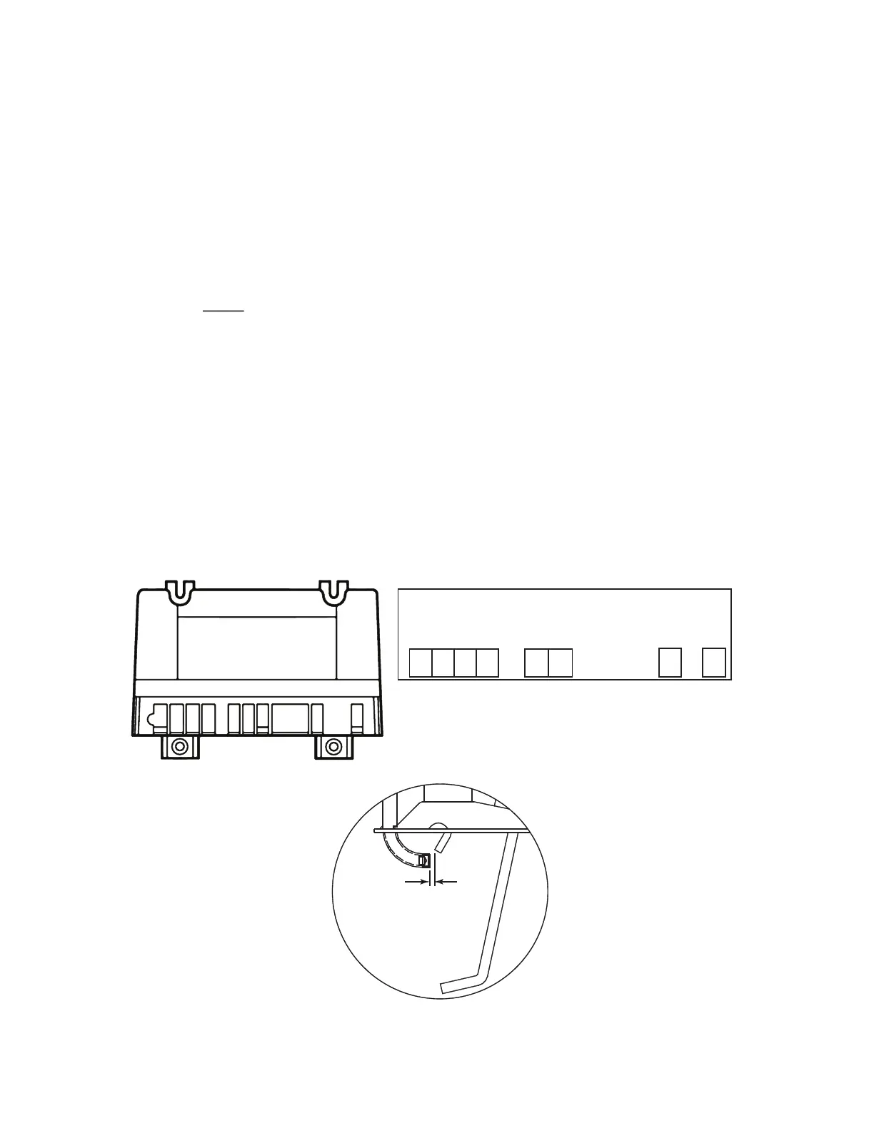
Figure 19 - Flame Safety Controller
MV
MV/PV
PV
GND
(BURNER)
24V
GND
24V
SENSE
SPARK
Terminals
1/8” to 3/16”
Proper Spark
Gap