8
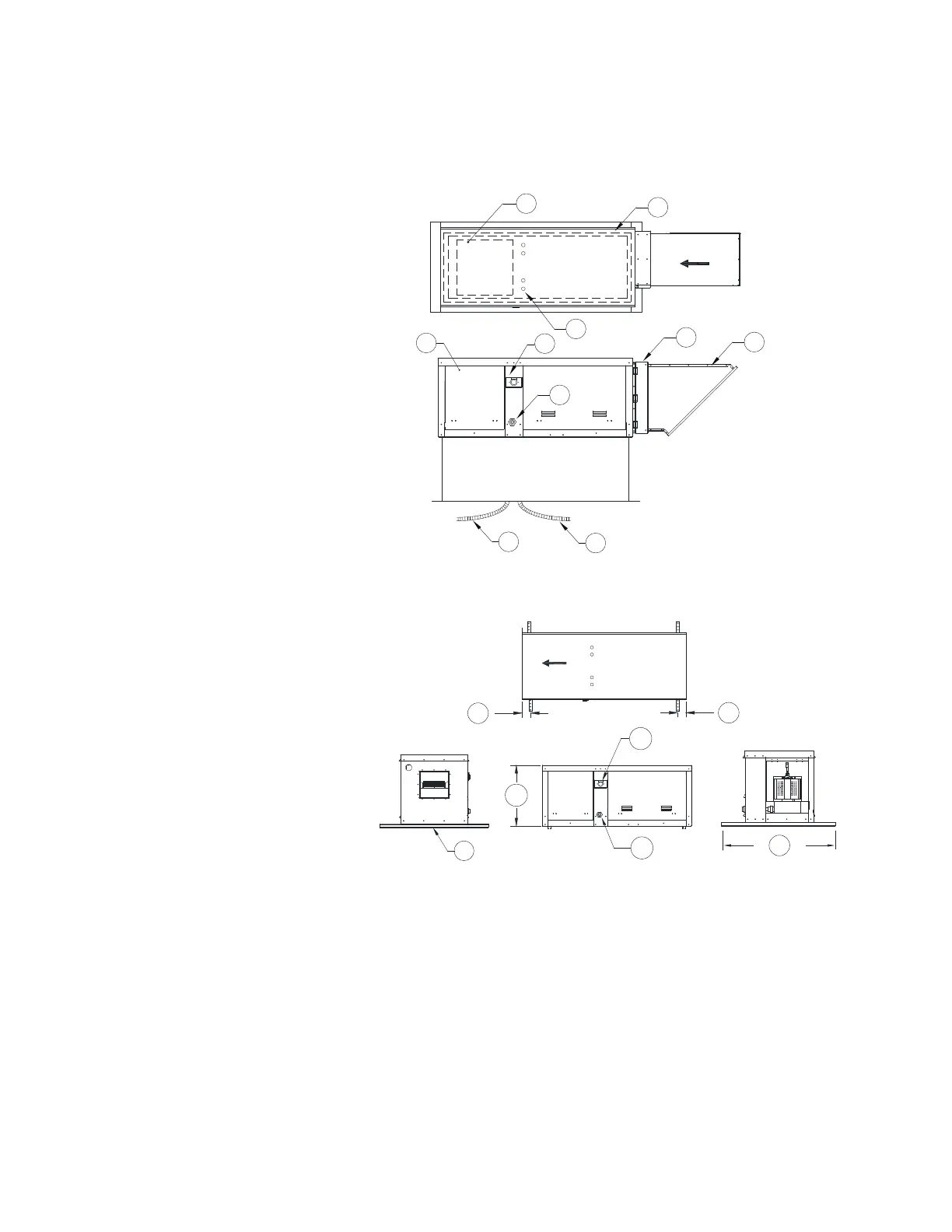
Roof Mount Installation
Note: Refer to submittal drawings for specific unit dimensions.
Figure 3 - Roof Mount Installation Details
Figure 4 - Indoor Inline
1. Discharge Opening
2. Curb Outer Wall
3. Flex Conduit for Field Wiring
4. Screened Intake
5. Filter Access Door
6. Service Disconnect Switch
7. 1/2” NPT Pipe
8. Blower/Motor Access Door
9. Control Drop
10. Motor Drop
1. Service Disconnect Switch
2. 1/2” NPT Pipe
3. Optional Unistrut Base for
Hanging
A. 1” Spacing from Unistrut to edge
of unit
B. 36” Unistrut
C. Unit Height
AIRFLOW
MOTOR
BLOWER/
DOOR
ACCESS
A
1
B
2
3
A
C