20
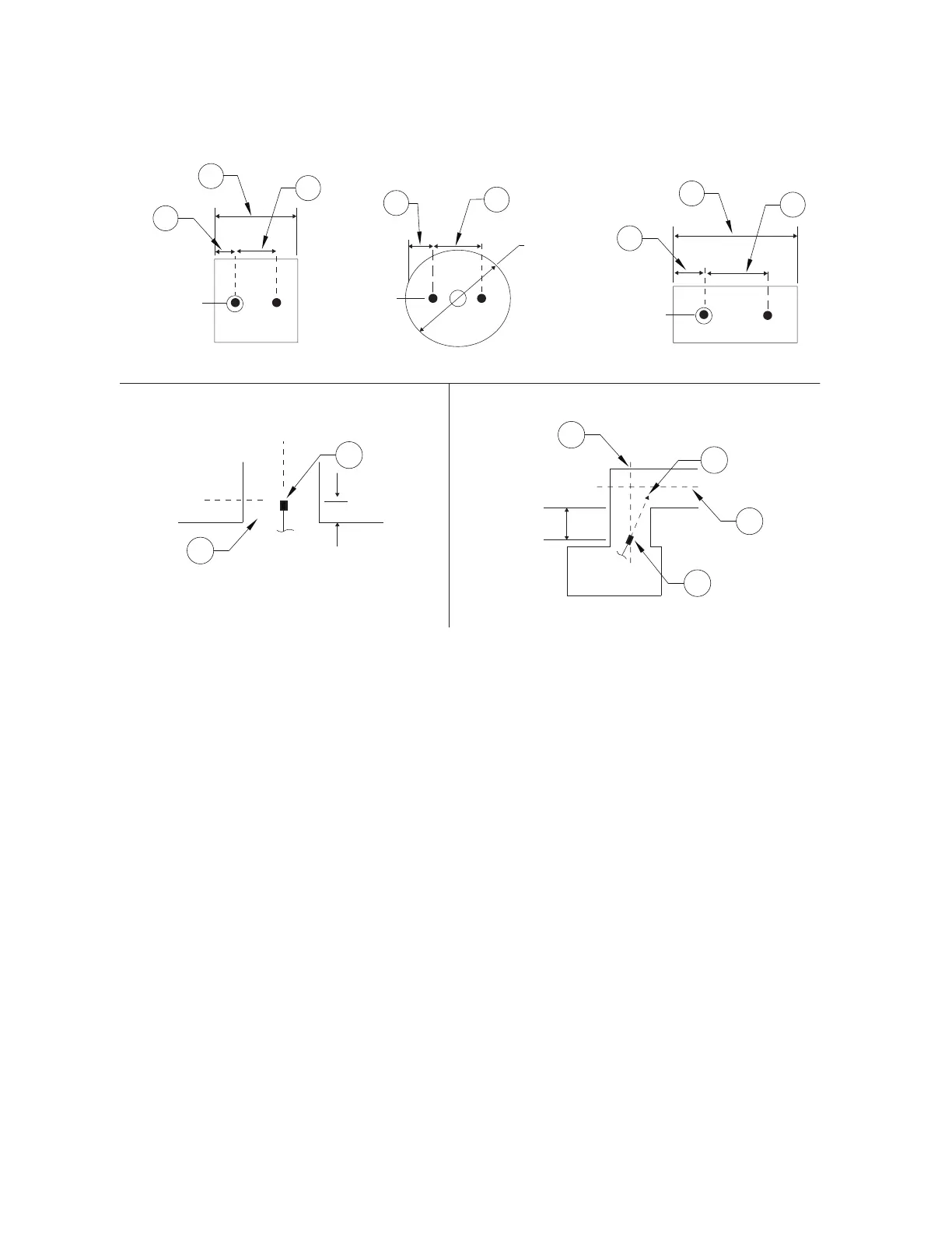
Figure 22 - Dual Nozzle Placement (50-100” Perimeter Duct)
Ventilation Exhaust and Dampers
The EWC extinguishing system can be used with the exhaust fan either on or off when the system is
discharged. It is recommended that the exhaust fan remain on at the time of discharge to aid in the
removal of smoke, gases, and other airborne materials from the hazard area in the event of a fire. A
damper, if present, should be left open at system discharge. However, if the damper is closed, the system
designer must make sure that additional nozzles are required.
Electrostatic Precipitators (ESP)
An Electrostatic Precipitator (ESP) is designed to remove smoke and other airborne contaminants from the
air flowing through the exhaust ductwork as a means of pollution control. Exhaust ductwork using ESPs
requires ADP nozzle(s) upstream (prior to) and immediately downstream of the ESP. The downstream
nozzle(s) must be located centrally in the ductwork and should be aimed at the middle of the ESP.
Distribution piping to the ADP nozzles must not interfere with the function of the ESP unit.
A Pollution Control Unit (PCU) and/or Electrostatic Precipitator (ESP) covered with this fire system can
utilize up to 12 flow points per tank.
1. ADP Nozzle
2. Vertical Duct Centerline (CL)
3. Aim Point
4. Horizontal Duct Centerline (CL)
5. Duct Entrance
A. 1/4 of dimension X
B. 1/2 of dimension X
C. 1/4 of Duct Diameter
D. 1/2 of Duct Diameter
L
C
L
C
L
C
L
C
L
C
L
C
L
C
L
C
L
C
X
X
A
C
A
B
D
B
L
C
L
C
L
C
L
C
5
1
1
3
4
2
32” Nom.
(809mm)
0-6” (0-152mm)
2-4”
(51-102mm)
Square Duct Round Duct Rectangular Duct
Vertical Duct Vertical/Horizontal Duct