58
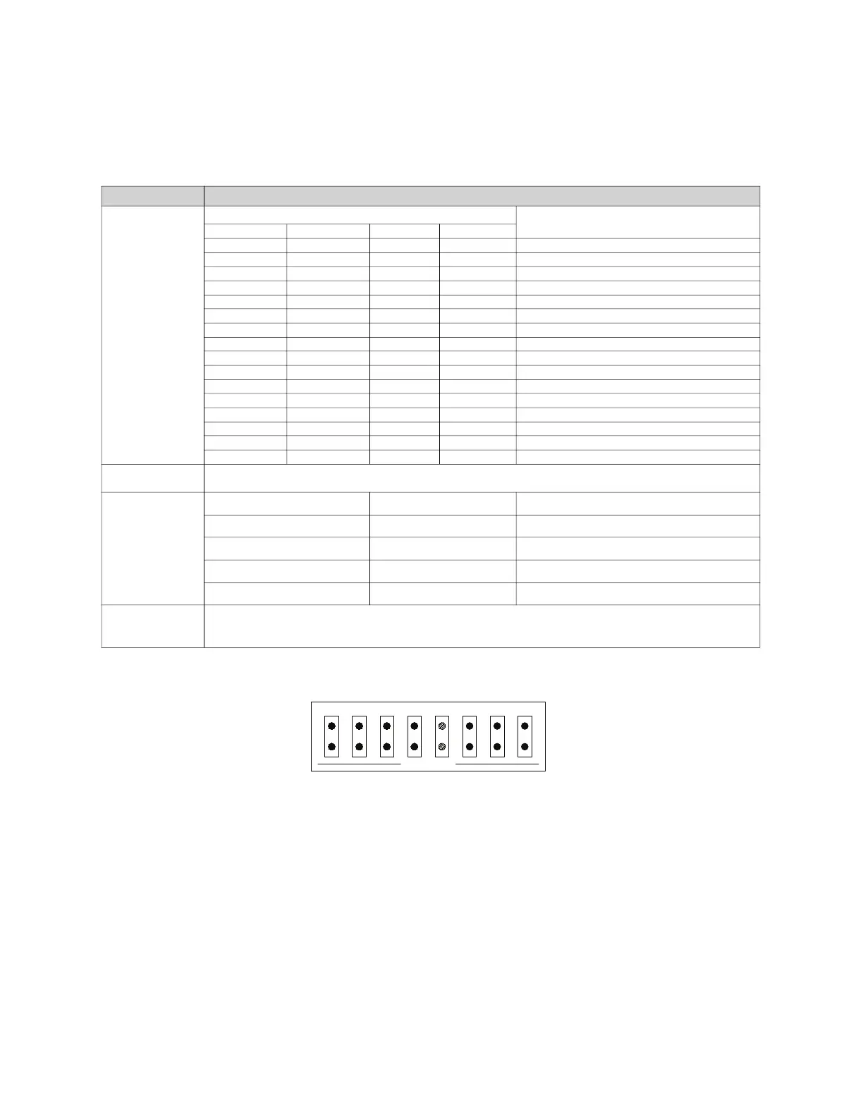
DIP Switch Settings
When set from the factory, switches 1, 5, and 8 are in the Closed (On) positions. Switch 2, 3, 4, 6, 7 are in
the Open (Off) position. These should be considered the default positions and should not be changed.
Figure 47 - DIP Switch
• Each unit has a unique address based on the DIP switch 1-4 settings, 15 units max on a network.
• If address is 0 (all switches off), the unit will not accept or send any network traffic.
• The unit that has switch 5 set to on will be the “master” and will be in charge of polling all the units
below it and waiting for a reply. The lack of 3 replies in a row will cause an “interlock network
supervision fault.” All units will be polled in a burst every 3 seconds.
• For all non-master units, the lack of being polled for 10 seconds will cause an “interlock network
supervision fault.”
• Any unit detecting a fire condition will broadcast the notification once every second for as long as the
condition persists.
• When the Fire condition is cleared, 10 notifications will be sent, one every second.
• Any unit detecting a supervisory fault will broadcast the notification every 2 seconds until the condition
is cleared.
• When the supervisory fault condition is cleared, 10 notifications will be sent, one every 2 seconds.
Table 21 - DIP Switch Settings
DIP Switch # Description
1 through 4
DIP Switch Position
Interlock Network Address
1 2 3 4
Closed Open Open Open 1
Open Closed Open Open 2
Closed Closed Open Open 3
Open Open Closed Open 4
Closed Open Closed Open 5
Open Closed Closed Open 6
Closed Closed Closed Open 7
Open Open Open Closed 8
Closed Open Open Closed 9
Open Closed Open Closed 10
Closed Closed Open Closed 11
Open Open Closed Closed 12
Closed Open Closed Closed 13
Open Closed Closed Closed 14
Closed Closed Closed Closed 15
Open Open Open Open This unit is not part of an interlock network
5
Set this switch to Closed (On) if this unit has the highest address on the interlock network. Otherwise, this
switch must be Open (Off)
6 and 7
Fire Group
6 7
Fire Group Number
Open Open
1
Closed Open
2
Open Closed
3
Closed Closed
4
8
Setting switch 8 to its Closed (On) position connects a 120 Ohm terminating resistor to the interlock network.
This switch must be Closed if this unit is at either physical end of the interlock network cable. Otherwise, it must
be Open (Off).
SW1