6
Cylinder Assembly
The EWC cylinder assembly (p/n 87-300001-001) uses a mild steel cylinder, conforming to 4BW250 DOT
& 4BWM-17 TC specifications, and a nickel-plated brass valve with pressure indicator gauge. Each valve
includes a Schrader port for connection to the primary actuator hose (for primary cylinders) or the optional
supervisory pressure switch (for secondary cylinders).
Each cylinder assembly is factory-filled with CAS liquid fire suppressant and pressurized to 200 PSIG
(1379 kPA) at 70°F (21°C). Each cylinder supports up to 6 flow points.
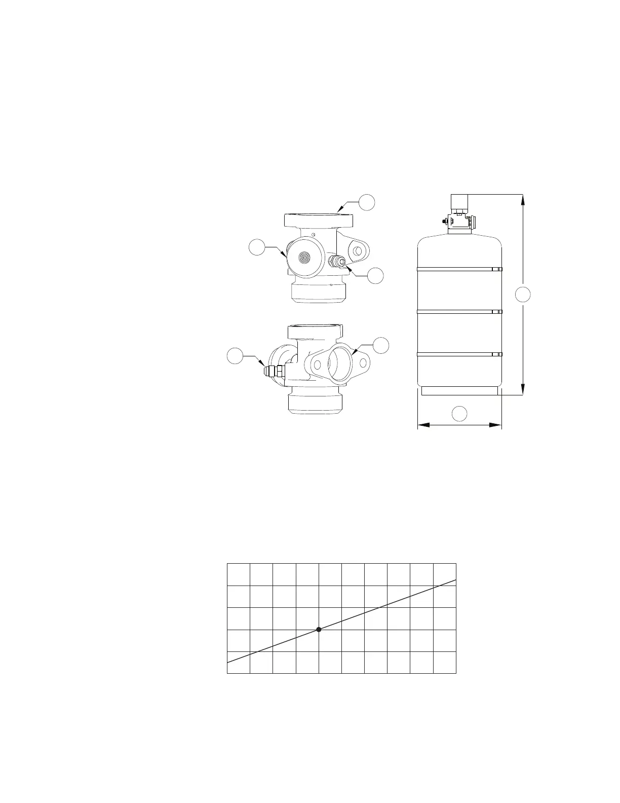
Figure 3 - Cylinder Tank Details
The pressure of a cylinder will vary with the ambient temperature, as detailed in Table 1. The gauge
indicator (shown in Figure 3) should be in the acceptable ‘green’ range for a cylinder that is properly
pressurized and within the listed operating temperature range. For a cylinder at the lowest listed operating
temperature of 32°F (0°C), the pressure gauge should read approximately 185 psig (the lower end of the
green range). For a cylinder at the highest listed operating temperature of 132°F (54.4°C), the pressure
gauge should read approximately 224 psig (the upper end of the green range).
Table 1 - Cylinder Temperature Vs Pressure
1. Valve Actuation Interface
2. Schrader Valve
3. Pressure Gauge
4. Discharge Outlet
A. Tank to Actuator Distance =
23-1/4”
B. Tank Diameter = 10”
230
(1586 kPA)
220
(1517 kPA)
210
(1448 kPA)
200
(1378 kPA)
190
(1309 kPA)
180
(1240 kPA)
30
(-1)
40
(4)
50
(10)
60
(15.6)
70
(21)
80
(27)
90
(32)
100
(38)
110
(43.3)
120
(49)
130
(54.4)
Temperature °F (°C)
Pressure PSIG (kPa)