57
Supervised Loop Wiring Troubleshooting
NOTE: Place the panel in test mode during diagnostic testing.
Prior to troubleshooting, verify all CORE power supplies are set to 27.5 volts. Check all supervised loop
connections. Verify wiring is properly connected and secure. If any of the “Normal Operating Voltages” are
out of range, there is an issue with that loop or associated components/wiring.
* Components that may cause this fault are: Gas Valve, Surfactant Pump, Water Solenoid(s),
Release Solenoid(s).
** Components that may cause this fault are: 24V Relays, Trouble Relay (when energized), 24V LED
Lights.
NOTE: If an abnormal reading is present, disconnect potential components/wiring one at a time,
while continuing to take readings, to pinpoint the source of the ground fault.
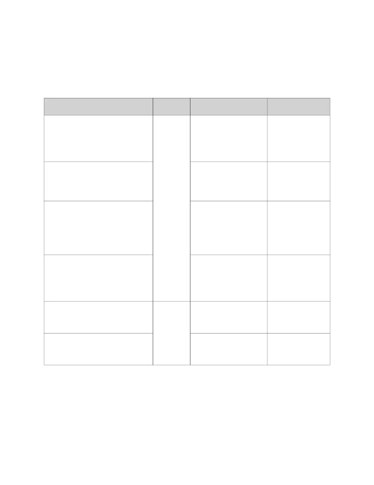
Normal Operating Voltages Problem Potential Cause
Corrective
Action
• Terminal 21 to CORE Power
Supply (-) = 26.5V
• Terminal 21 to Terminal 22 = 26.5V
• Terminal 24 to Power Supply (-) =
26.5V
• Terminal 24 to Ground = 1.8V
Supervised
Loop Fault
Open Supervised Loop
between Terminals 21 and
24
Locate and repair
faulty wiring in the
21-24 supervised
loop.
• Terminal 22 to CORE Power
Supply (-) = 0V
• Terminal 23 to CORE Power
Supply (-) = 0V
• Terminal 23 to Terminal 24 = 26.5V
Open Supervised Loop
between Terminals 22 and
23
Locate and repair
faulty wiring in the
22-23 supervised
loop.
• Terminal 101 to CORE Power
Supply (-) = 26.5V
• Terminal 101 to Terminal 102 =
26.5V
• Terminal 104 to CORE Power
Supply (-) = 26.5V
• Terminal 104 to Ground = 1.8V
Open Supervised Loop
Push-Station (Terminals
101 and 104)
Locate and repair
faulty wiring in the
101-104 supervised
loop.
• Terminal 102 to CORE Power
Supply (-) = 0V
• Terminal 103 to CORE Power
Supply (-) = 0V
• Terminal 103 to Terminal 104 =
26.5V
Open Supervised Loop
Push-Station (Terminals
102 and 103)
Locate and repair
faulty wiring in the
102-103 supervised
loop.
Chassis Ground to CORE Power
Supply (-) = 24.4V
Ground
Fault
*24V DC CORE Power
Supply (-) Wiring or
Components
Locate and repair
faulty wiring in the
22-23 supervised
loop.
Chassis Ground to CORE Power
Supply (+) = 2.7V
**24V DC CORE Power
Supply (+) Wiring or
Components
Locate and repair
faulty wiring in the
21-24 supervised
loop.