60
INSPECTION AND TEST
Once installation has been completed, the EWC suppression system must be checked for proper
installation and operation before it can be put into service.
Start-up/Test Procedure
Preparing System for Test
1. Verify that all solenoid wires are secured and not touching hood.
2. Place the control panel in test mode and ensure there are no supervision faults.
3. Verify that the hood, duct & kitchen appliances have not changed (including type, dimensions &
location) from the approved design.
4. Verify that all cylinder discharge outlets are connected to the system piping, refer to Figure 3 on
page 6.
5. Verify that all cylinders are secured in their bracket(s).
6. Verify that the vent plug is properly installed, refer to Figure 14 on page 13.
7. Verify that a valve cap or optional supervisory pressure switch is installed on each secondary cylinder
Schrader valve port.
8. Verify that nozzle caps are installed, and foil seals are intact on all nozzles, refer to Figure 9 on
page 10.
Connecting Service Test Tank to the System
CAUTION!: Supplied Nitrogen Pressure Must be 25 psig Minimum to 200 psig Maximum.
Refer to “COMPONENTS” on page 5 for component location and details.
1. Disconnect the Primary Actuator Kit (PAK) stainless-steel hose from the primary cylinder valve.
NOTE: When disconnecting or re-attaching primary hose, perform action quickly to minimize
nitrogen loss.
2. Verify that the Supervisory Pressure Switches have activated.
3. Remove the PAK and any Secondary Valve Actuators (SVA) from their cylinder. Place PAK and SVAs
in the ship/test position. Verify that the PAK and SVAs are securely mounted to the bracket. Refer to
Figure 15 on page 13.
4. Connect the stainless steel hose from the PAK assembly to a Nitrogen Service Cylinder via the
1/4” refrigerant test hose with 1/4” male thread union. Refer to Figure 48.
5. Connect an additional 1/4” refrigerant test hose from the service port of the PAK assembly to the
service port on the fire system distribution piping.
6. Verify that the pistons in the PAK and SVAs are in the set position. Refer to Figure 16 on page 14.
7. Verify all secondary actuator hoses are connected to the appropriate PAK or SVAs and are securely
tightened.
8. Verify the actuation line plug is installed in the last actuator on the system (last SVA or PAK if there are
no secondary cylinders). Verify the plug is tight.
9. Verify that the Supervisory Pressure Switch is installed securely on the PAK. Optional Feature:
Secondary tanks may also have Supervisory Pressure Switches installed, verify all switches are
properly secured to all secondary tanks.
10. Verify the primary actuator solenoid is in the de-energized state.
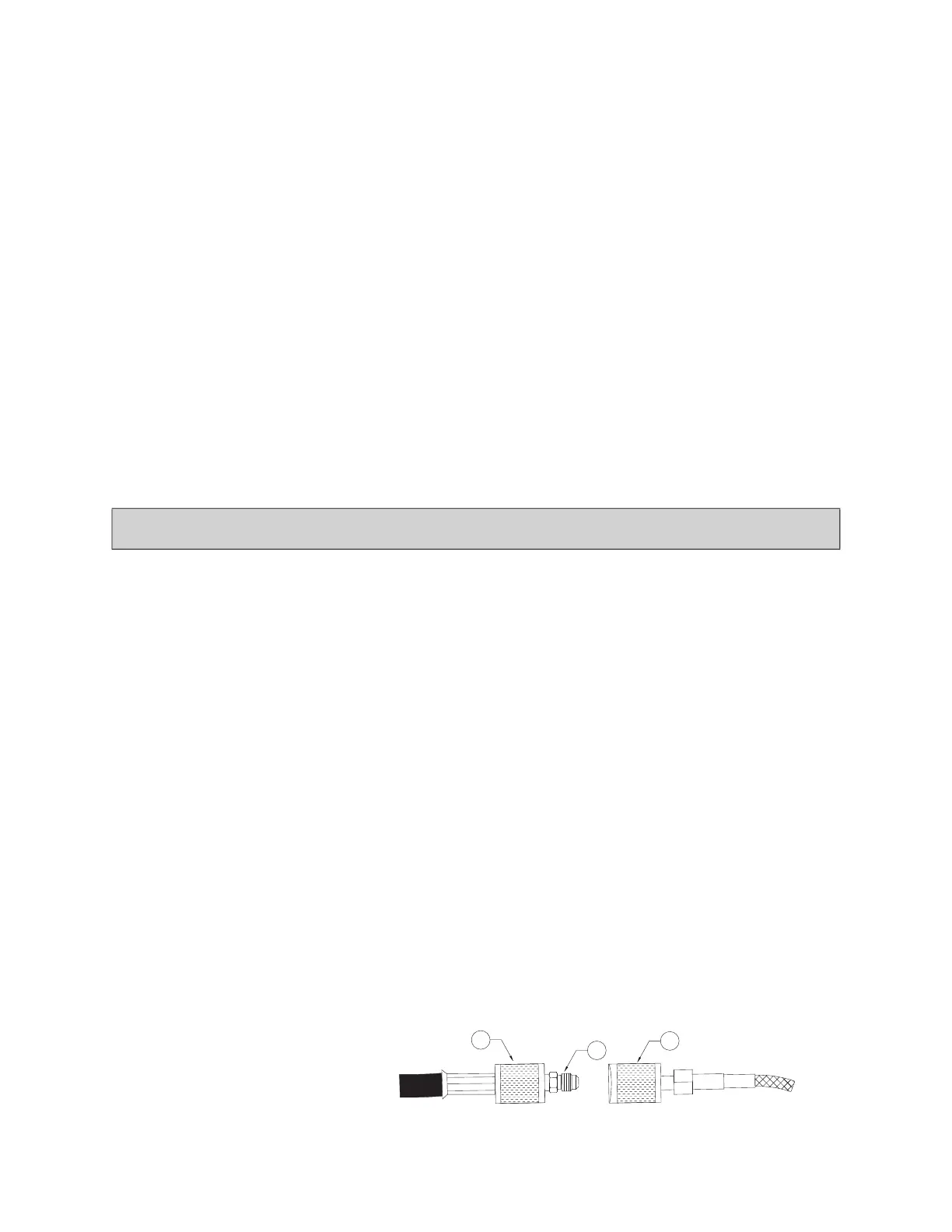
Figure 48 - PAK Connection to Test Hose
Warning!
If the PAK or SVAs are installed on the cylinder valve during the test, the cylinders will discharge.
1. 1/4” Refrigerant Test Hose
2. 1/4” Male to Male Union
3. PAK Connection Hose