46
Connector Descriptions
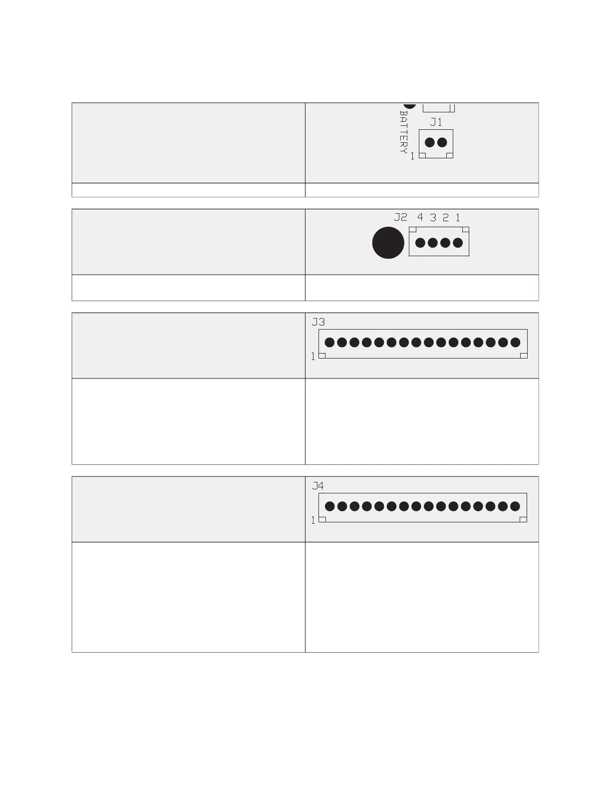
Note: Some connections may not be used dependent on system configurations.
Connector J1 contains battery pack connections for
battery charging and monitoring.
Pin 1 – Battery Positive Pin 2 – Battery Negative
Connector J2 contains Supervised Sensor Loop
connections
Pin 1 – Start Positive Loop
Pin 2 – Start Negative Loop
Pin 3 – Finish Negative Loop
Pin 4 – Finish Positive Loop
Connector J3 contains Power Supply and Device
connections
Pin 1 and Pin 2 – Positive Input, Power Supply
Pin 3 and Pin 4 – Negative Input, Power Supply
Pin 5 – Positive Output, Gas Valve Solenoid
Pin 6 – Positive Output, Surfactant Pump
Pin 7 – Positive Output, Release Valve Solenoid
Pin 8 and Pin 9 – 24V DC Input, Shutoff Valve
Supervision
Pin 10 – N/A
Pin 11 – Drive Output, Fire Relay
Pin 12 – Drive Output, 100% Relay
Pin 13 – Drive Output, Trouble Relay
Pin 14 – Drive Output, Wash Relay
Pin 15 – Drive Output, Spare Relay
Pin 16 – Drive Output, Auto-Man Relay
Connector J4 contains Power Supply and Device
connections
Pin 1 – Positive Input, Power Supply
Pin 2 – Output, Panel Mounted Audible Alarm
Pin 3 – Output, Panel Mounted LED Fire/Fault
Indicator
Pin 4 – N/A
Pin 5 – Drive Output, Cooking Equipment Disable
Relay
Pin 6 – Negative Input, Power Supply
Pin 7 – N/A
Pin 8 – Input, Pump Prime/Reset Push Button
Pin 9 – Input, Gas Cartridge/Pressure Switch
Pin 10 – Input, Fan Switch
Pin 11 – Input, Gas Valve Reset Push Button
Pin 12 – Input, Door/Tamper Switch
Pin 13 – Input, Test Mode
Pin 14 – Modbus Network, Common Signal (C)
Pin 15 – Modbus Network, Negative Signal (A)
Pin 16 – Modbus Network, Positive Signal (B)