docs.carbide3d.com support@carbide3d.com 37
Install the Proximity
Switches
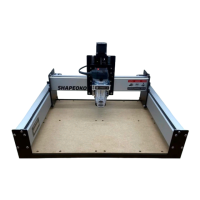
switches. The Z-Axis proximity switch is
pre-installed on the front of the Z-Plus. See
Figure6‑4. The X- and Y-Axis proximity switches
will be attached to mounting plates and then
Label the Z-Axis Proximity Switch
1. Use the included permanent marker to label
the Z-Axis proximity switch cable connector
with a “Z” as shown in Figure6‑4.
Install the X-Axis Proximity Switch
of their black lead cables. The X-Axis proximity
to the X-Axis proximity switch mounting plate, then
mounted to the BACK of the Z-Plus.
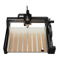
1. Locate the X-Axis proximity switch, with the
longer lead cable, and its mounting plate, the
taller of the two plates.
2. Align the switch and plate, with the switch
facing left and the plate’s two PEM nuts in
the BOTTOM-RIGHT corner. Flush the face
of the switch with the edge of the plate. See
Figure6‑5.
3. ×18mm
socket head cap screws to attach the switch
to the plate. Make sure the front edge of the
Figure6‑5.
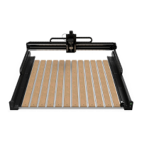
4. ×8mm
socket head cap screws to install the mounting
plate to the two 30mm standoffs at the rear of
the Z-Plus. Ensure the proximity switch is on
the outside of the switch plate and faces the
Y2-rail. See Figure6‑6.
5. Label the X-Axis proximity switch cable
connector with an “X” as shown in Figure6‑6.
Install the Y-Axis Proximity Switch
The Y-Axis proximity switch has the shorter
cable. It attaches to the Y-Axis proximity switch
mounting plate then attaches to the OUTSIDE of
the Y2-carriage.
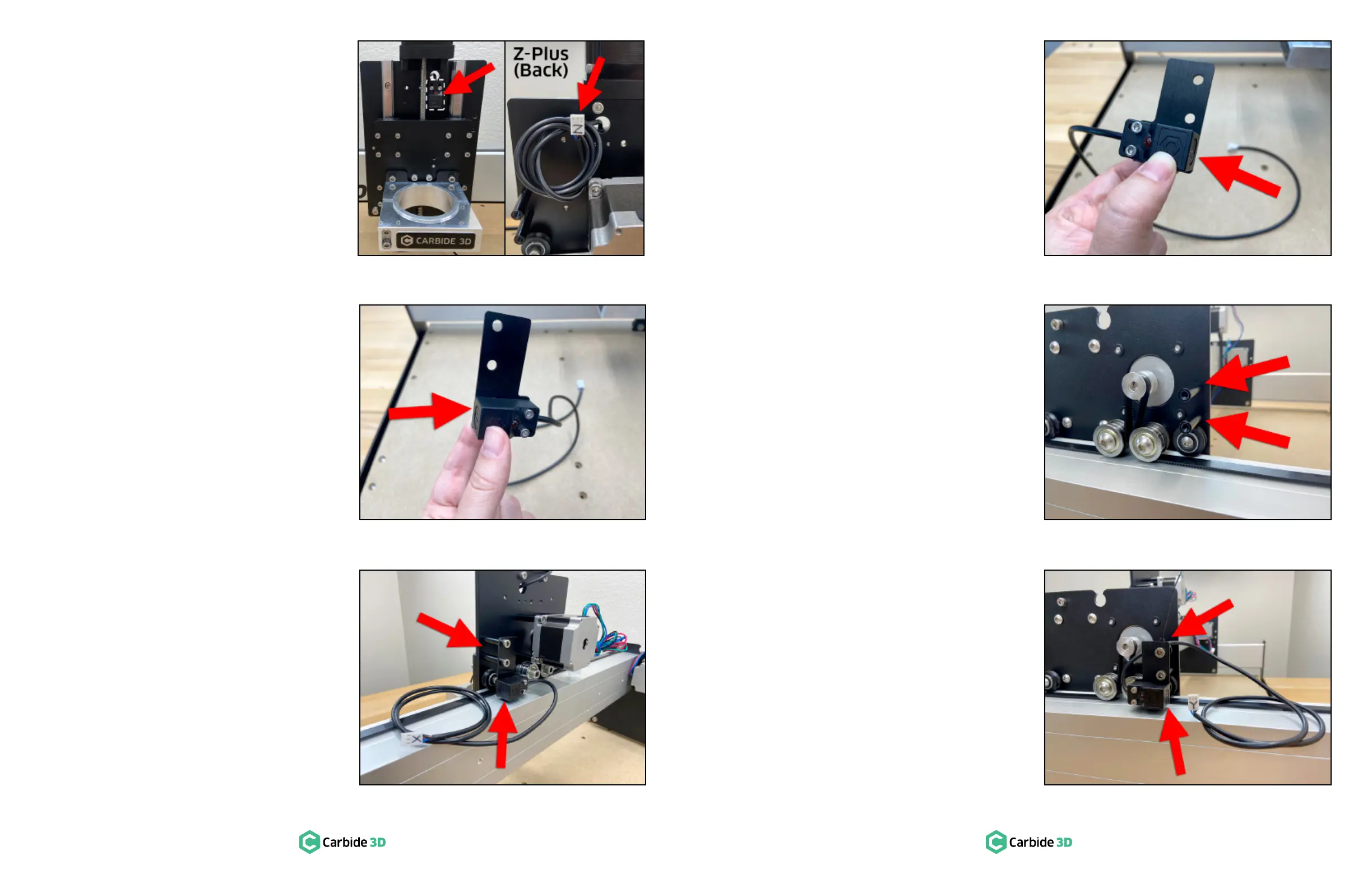
1. Locate the remaining Y-Axis proximity switch,
with the shorter lead cable, and its mounting
plate, the shorter of the two plates.
2. Align the switch and plate, with the switch
facing right and the plate’s two PEM nuts in
the BOTTOM-LEFT corner. Flush the face of
the switch with the edge of the plate. See
Figure6‑7.
3. ×18mm
socket head cap screws to attach the switch
to the plate. Make sure the front edge of the
Figure6‑7.
4.
standoffs to the OUTSIDE of the Y2-carriage.
See Figure6‑8.
5. ×8mm
socket head cap screws to install the mounting
plate to the two 30mm standoffs on the
OUTSIDE of the Y2-rail, with the switch to the
outside of the plate and facing the rear. See
Figure6‑9.
switch cable to the upper standoff. See
Figure6‑9.
7. Label the Y-Axis proximity switch cable
connector with a “Y” as shown in Figure6‑9.
Figure6-5
Figure6-4
Figure6-6
Figure6-7
Figure6-8
Figure6-9
 Loading...