34 docs.carbide3d.com support@carbide3d.com 35
Required Components
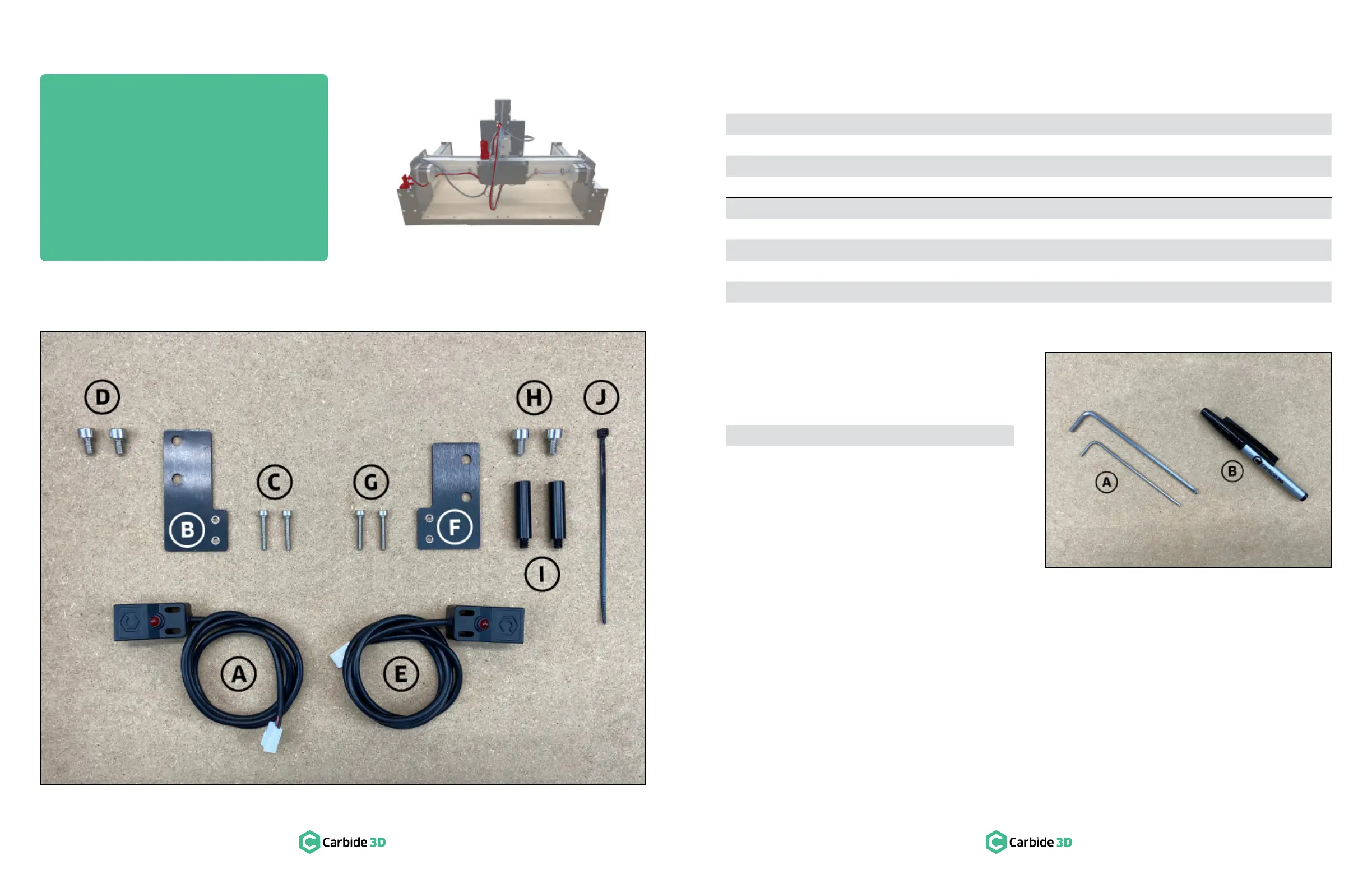
See Figure6‑2:
Item Description Location Qty
A X-Axis Proximity Switch Shapeoko 3 Final Assembly Box 1
B X-Axis Proximity Switch Plate Shapeoko 3 Final Assembly Box 1
C M3 × 18mm Socket Head Cap Screw Shapeoko 3 Final Assembly Box 2
D M5 × 8mm Socket Head Cap Screw Shapeoko 3 Final Assembly Box 2
E Y-Axis Proximity Switch Shapeoko 3 Final Assembly Box 1
F Y-Axis Proximity Switch Plate Shapeoko 3 Final Assembly Box 1
G M3 × 18mm Socket Head Cap Screw Shapeoko 3 Final Assembly Box 2
H M5 × 8mm Socket Head Cap Screw Shapeoko 3 Final Assembly Box 2
I 30mm Male-to-Female Standoff Shapeoko 3 Final Assembly Box 2
J Cable tie Shapeoko 3 Final Assembly Box 1
Required Tools
See Figure6‑3:
Item Description Qty
A 2.5 and 4mm Hex Key 2
B Permanent Marker 1
Figure6-2
Figure6-3
Step 6
Proximity Switches
 Loading...