32 docs.carbide3d.com support@carbide3d.com 33
12. ×10mm
socket head cap screw to attach the belt clip
to the Y2-carriage. Insert the screw from the
OUTSIDE
as this could bend the X-motor pulley. See
Figure5‑11.
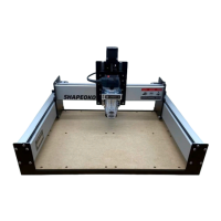
Install the Y1‑Rail Belt
1. Attach a belt clip to one end of one of the two
remaining belts. (Refer back to Figure5‑4
2. Set the belt clip on top of the Y1-rail next to
teeth down, and extend along the Y1-rail
towards the Y1-carriage. Ensure the teeth of
the bottom 2 inches of belt interlock with the
top. See Figure5‑12.
3. ×10mm
socket head cap screw to attach the belt clip
to the front endplate. Insert the screw from the
FRONT and tighten. See Figure5‑12.
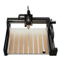
4. Feed the belt under the two idlers on the
outside of the Y1-carriage. Make sure the belt
does not twist and the teeth remain facing
down all the way to the rear endplate. See
Figure5‑13.
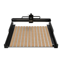
5. Slide the 3mm hex key under the belt, between
Y1-rail to push a loop of belt up between the
two idlers as shown in Figure5‑14.
Use the 3mm hex key to hook the belt and pull
it up between the two idlers.
7. Make sure the belt has not twisted and
the teeth are still facing down, then place
Figure5‑15.
8. Very gently take the slack out of the belt by
slowly pulling the free end toward the rear
endplate.
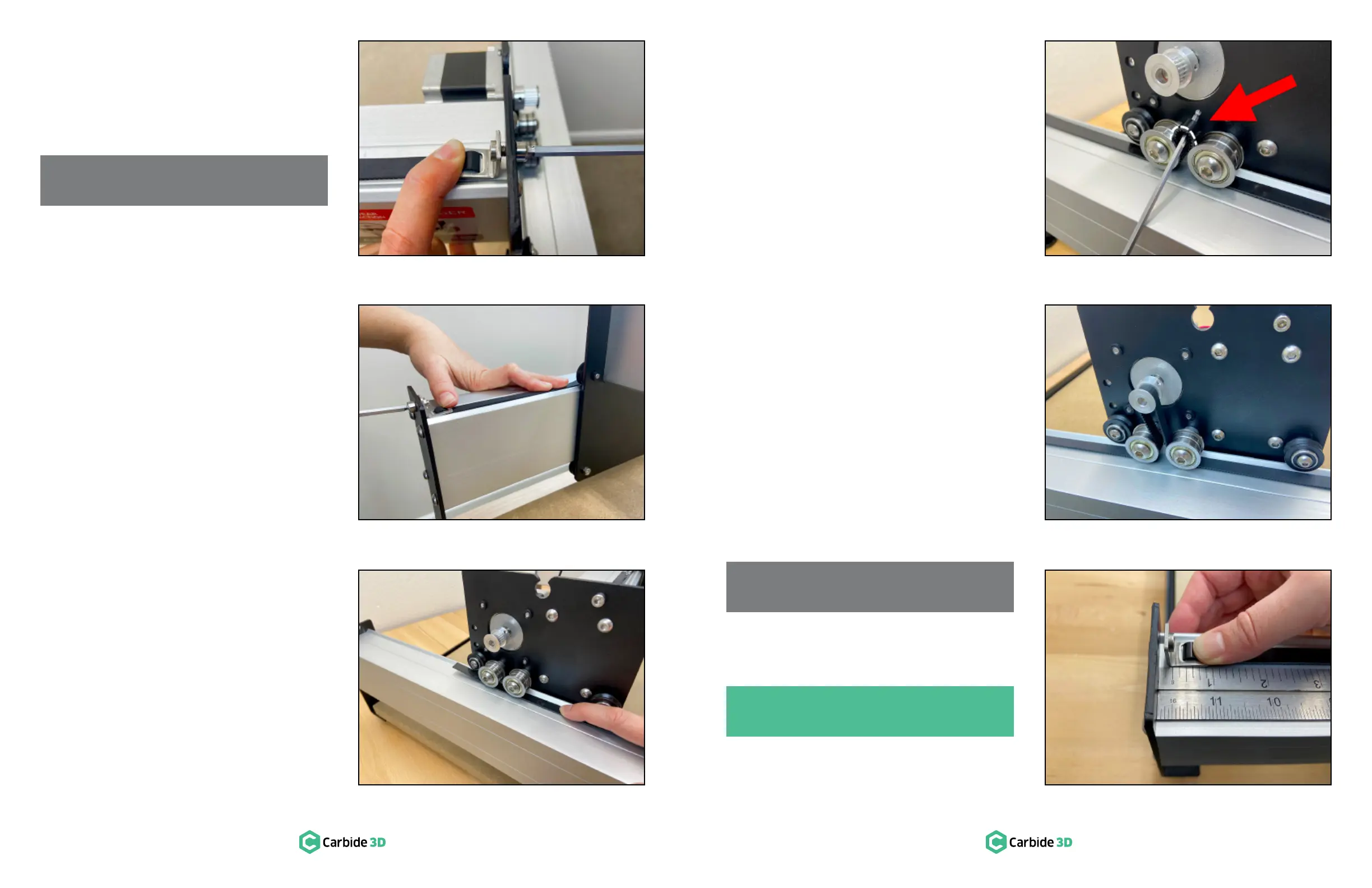
Attach another belt clip to the free end of the
belt. (Refer back to Figure5‑4
10. Adjust the amount of belt you feed through
/-inch gap exists
between the belt clip and the rear endplate.
Ensure the teeth of the bottom few inches of
belt interlock with the top. See Figure5‑16.
11. ×10mm
socket head cap screw to attach the belt clip
to the rear endplate. Insert the screw from the
BACK
could bend the Y1-motor pulley.
Install the Y2‑Rail Belt
1. Install the remaining belt on the Y2-rail,
following steps 1-11 of the “Install the Y1-Rail
PRO TIP: The Y2-belt installation is a mirror
image of the Y1-belt process.
NOTE: The belt should be tight enough to
snap against the Y1-rail when gently lifted.
NOTE: The belt should be tight enough to
snap against the X-rail when gently lifted.
Figure5-11
Figure5-12
Figure5-13
Figure5-14
Figure5-15
Figure5-16
 Loading...