40 docs.carbide3d.com support@carbide3d.com 41
Install the PCB Riser Board
The PCB riser board is required to connect the
Carbide Motion board.
1.
screw.
×12mm button
head cap screws. They are for mounting it to the
X-rail. Set them aside for now.
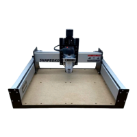
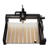
2. Plug the PCB riser board into the 2×8 bank
of pins in the BOTTOM-LEFT corner of the
Carbide Motion board as shown in Figures7‑5
and 7‑6.
Mount the Enclosure
1. Position the enclosure on the BACK of the
X-rail, with the USB and power ports facing
the Y1-RAIL. All printed text on the Carbide
Motion board will be UPSIDE-DOWN.
2.
×12mm button head cap screws to mount
the enclosure. See Figure7‑6.
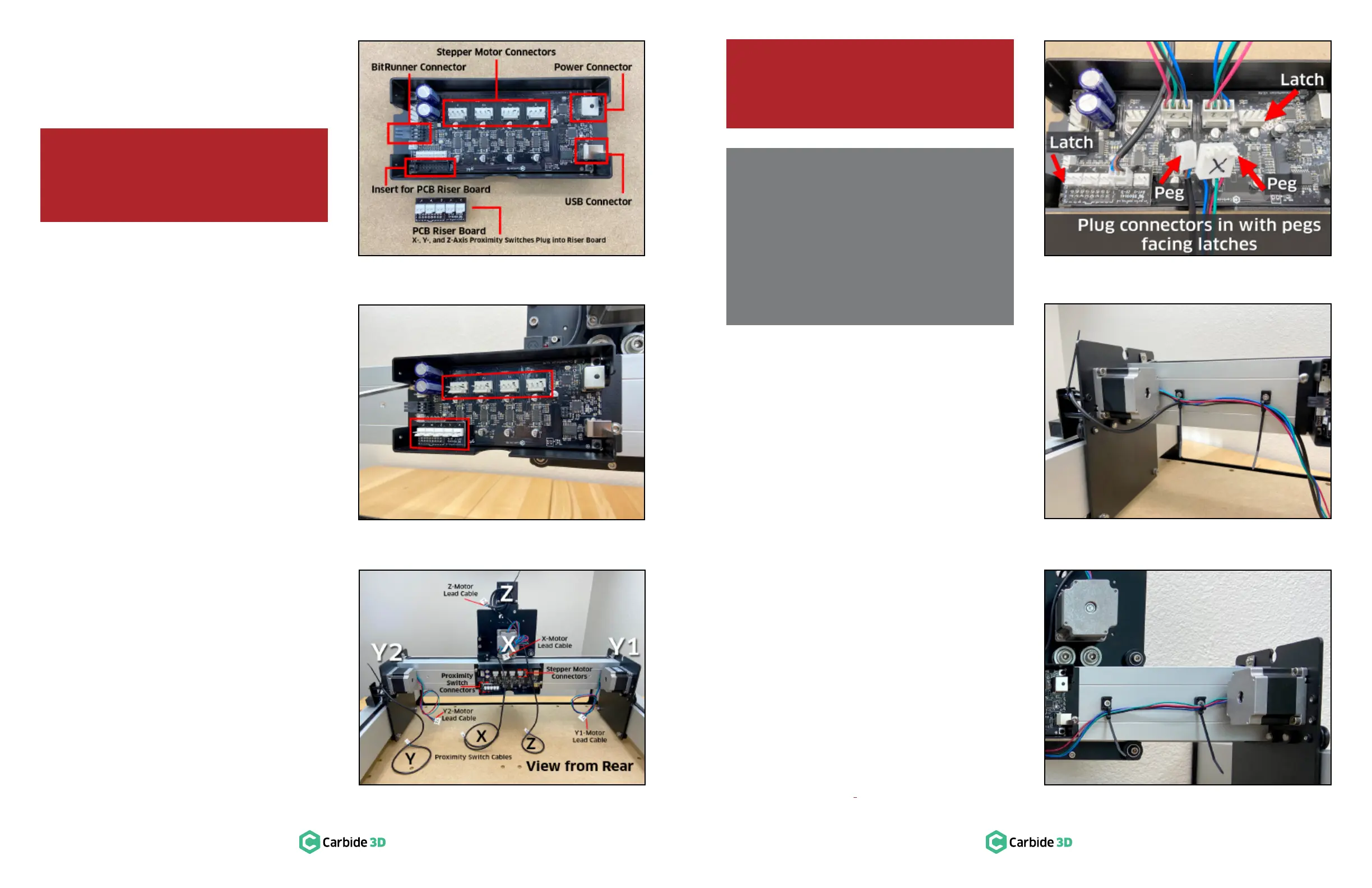
Identify Cables and Label
Stepper Motor Connectors
1. Familiarize yourself with the location of each
stepper motor and proximity switch cable
shown in Figure7‑7.
2. Use the permanent marker to label each of
the four stepper motor connectors with the
appropriate label, “X,” “Y1,” “Y2,” or “Z,” as
shown in Figure7‑7.
Secure and Connect Y‑Axis Cables
Before plugging the Y-Axis cables into the Carbide
Motion board, we will be securing them to the X-rail
using cable ties and cable tie mounts.
Secure the Y-Axis Cables
1. ×
socket head cap screw to attach each of the
screw holes across the back of the X-rail.
either side of the enclosure. See Figure7‑9
and 7‑10.
Each cable tie mount has two attachment points,
an upper and a lower, for cable ties.
2.
3.
lead cable and the Y-Axis proximity switch
cable to the two mounts closest to the
Y2-motor. Use the lower attachment points.
See Figure7‑9.
4.
lead cable to the lower attachment points on
the remaining two
mounts. See Figure7‑10.
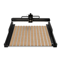
Polarized Connectors Explained
At the end of each cable is a female connector with
two alignment pegs. These alignment pegs must face
the latches of the corresponding male connectors on
the Carbide Motion board. See Figure7‑8.
The four stepper motor cables plug into connectors
at the top of the Carbide Motion board. The three
proximity switch cables plug into the PCB riser board,
installed in the bottom (Y2) corner of the Carbide
Motion board. See Figure7‑5 and 7‑8.
WARNING: When removing the enclosure
cover, pry open from the USB/power end rst,
then open like a book to avoid damaging
the protruding Bitrunner connector. See
Figure7‑5.
WARNING: All connectors are polarized; they
can only be connected in one way. Connecting
the wrong way will damage the machine. DO
NOT FORCE A CONNECTION. See Figure7‑8.
Figure7-6
Figure7-5
Figure7-9
Figure7-10
Figure7-8
Figure7-7
 Loading...